 Bosnia and Herzegovina


Composition of the assembled group 000010
Series MX
Components:
Lockable isolation 3/2-way valve
Filter-regulator
Lockable isolation 3/2-way valve
Soft start valve + pressure switch (NO)
Lockable isolation 3/2-way valve
Filter-regulator
Lockable isolation 3/2-way valve
Soft start valve + pressure switch (NO)
 Download catalogue
Series
Accessories
there are no salable codes online
If you have entered Filters, try changing them or look in the "Configurator" tab

Kit wall brckts + flngs s.mx - MX2-1/2-KK


End-plate flanges (pair)s.mx - MX2-1/2-FL
In-out flanges kit - MX2-3/4-FL
In-out flanges kit - MX2-3/8-FL
In-out flanges kit - MX3-3/4-FL

Rap.clamps+flanges kit s. mx - MX2-1/2-JJ


Quantity added:
addtocart.popup.message.success
The requested quantity is partially confirmed
Product {0} is already in your cart with quantity {1}. You can update the quantity from cart page.
Product is not active
The product could not be added to the cart due to insufficient stock
Quantity must be greater than zero
Min allowed quantity for product {0} is {1}
Max allowed quantity for product {0} is {1}
Pack size for product {0} is {1}
It is not possible to add the product with code {0} to this cart
An error occurred, please try again later or contact customer support

Full screen

Coding example
| MX | 2 | - | 1 /2 | - | V01 | X | F00 | X | V1841AB | - | KK | - | LH |
| MX | SERIES | |||
| 2 | (1) |
SIZES 2 = G3/8 - G1/2 - G3/4 3 = G3/4 - G1 |
||
| 1 /2 | (2) |
IN / OUT THREADS 3/8 = G3/8 1/2 = G1/2 3/4 = G3/4 1 = G1 |
||
| V01 | (3) |
MODULE + [+] (to configure the modules, see the single components pages): |
F…= Filter FC... = Coalescing filter FCA... = Activated carbons filte R... = Pressure regulator L... = Lubricator FR... = Filter-Regulator |
V... = Lockable isolation valve V16..; V17..; V18..; V19.. = Machinery Directive solenoid valves (use version without mounting accessories) (only for MX2) AV... = Soft start valve B... = Take-off block (MX2: G1/2 only - MX3: G1 only) |
| [ * ] |
The following ACCESSORIES can be added after every single module: REGULATOR AND FILTER-REGULATOR MX2 +A12 = SWCN-P10-P3-2 (Electronic pressure switch) +A13 = SWCN-P10-P4-2 (Electronic pressure switch) +A14 = SWCN-P10-P4-M (Electronic pressure switch) +A52 = PG010-PB-1/8 (Pressure gauge) +A53 = PG010-PB-1/8-2 (Pressure gauge) +A54 = PG010-PB-1/8-M (Pressure gauge +A55 = M053-P04 (Pressure gauge) +A56 = M053-P06 (Pressure gauge) +A57 = M053-P10 (Pressure gauge) +A58 = M063-P12 (Pressure gauge) |
REGULATOR AND FILTER-REGULATOR MX3 +A15 = SWCN-P10-P3-2 (Electronic pressure switch) +A16 = SWCN-P10-P4-2 (Electronic pressure switch) +A17 = SWCN-P10-P4-M (Electronic pressure switch) +A59 = M063-P04 (Pressure gauge) +A60 = M063-P06 (Pressure gauge) +A61 = M063-P12 (Pressure gauge) +A62 = PG010-PB-1/4 (Pressure gauge) +A63 = PG010-PB-1/8-2 (Pressure gauge) +A64 = PG010-PB-1/8-M (Pressure gauge) |
||
|
LOCKABLE ISOLATION VALVE MX2 +A30 = 2901 1/2’’ (Silencier) +A31 = 2921 1/2’’ (Silencier) +A32 = 2931 1/2’’ (Silencier) +A33 = 2928 1/2’’ (Silencier) |
LOCKABLE ISOLATION VALVE MX3 +A34 = 2901 3/4’’ (Silencier) +A35 = 2921 3/4’’ (Silencier) +A36 = 2931 3/4’’ (Silencier) +A37 = 2928 3/4’’ (Silencier) |
|||
|
SOFT START VALVE +A00 = PM11-NA (Pressure switch, normally open) +A01 = PM11-NC (Pressure switch, normally closed) +A04 = PM11-SC (Pressure switch) +A05 = PM681-1 (Pressure switch) +A18 = PM681-3 (Pressure switch) |
||||
|
TAKE-OFF BLOCK MX2 +A11 = PM681-1 (Pressure switch) +A24 = PM681-3 (Pressure switch +A08 = PM11-NA (normally open pressure switch) with fitting for fixing to the module +A09 = PM11-NC (normally closed pressure switch) with fitting for fixing to the module +A03 = PM11-SC with fitting for fixing to the module Example: MX2-3/8-V01+A32XF00-KK-LH |
TAKE-OFF BLOCK MX3 +A06 = PM11-NA (normally open pressure switch) with fitting for fixing to the module +A07 = PM11-NC (normally closed pressure switch) with fitting for fixing to the module +A10 = PM681-1 (Pressure switch) +A25 = PM681+3 (Pressure switch) +A02 = PM11-SC with fitting for fixing to the module Example: MX3-3/4-V01+A36XF00-KK-LH |
ISOLATION VALVE MX2 / MX3 +A40 = U7H Coil UL (12V DC) +A41 = U77 Coil UL (24V DC) +A42 = U79 Coil UL (48V DC) +A43 = U7K Coil UL (110V AC) +A44 = U7J Coil UL (230V AC) +A45 = G7H Coil (12V DC) +A46 = G77 Coil (24V DC) +A47 = G79 Coil (48V DC) +A48 = G7K Coil (110V AC) +A49 = G7J Coil (230V AC) |
||
| X | (4) |
MODULES CONNECTION (according to the positioning scheme on the following page): X = Rapid clamp kit Z = Rapid clamp kit with wall fixing screw Y = Rapid clamp kit with wall fixing brackets |
||
| F00 | (5) + [ * ] | see MODULE (3) | ||
| X | (4) | |||
| V1841AB | (5) + [ * ] | see FORM (3) - if other forms are present | ||
| KK | (6) |
TERMINAL CONNECTIONS + [ ** ] = no terminal connection HH = n° 1 rapid clamp kit with flanges (IN / OUT) JJ = n° 1 rapid clamp kit with wall fixing screws + flanges (IN / OUT) KK = n° 1 rapid clamp kit with wall fixing brackets + flanges (IN / OUT) |
||
| [ ** ] |
WALL CONNECTION: REGULATOR and FILTER-REGULATOR S = Bracket (only with clamps mod. X o HH) Codes examples: MX3-1-R..XV..-S ; MX3-1-R..XV..-HSH |
|||
| LH | (7) |
FLOW DIRECTION: = from left to right (standard) LH = from right to left |
||
| (4) + (5) + [ * ] | REPEATABLE COMBINATION for a “n” number of times |
Coding example
| MX | 2 | - | 3/8 | - | 000001 |
| MX | SERIES |
| 2 |
SIZE 2 = G3/8 - G1/2 - G3/4 3 = G3/4 - G1 |
| 3/8 |
PORTS: 3/8 = G3/8 1/2 = G1/2 3/4 = G3/4 1 = G1 |
| 000001 |
GROUP COMPOSITION: 000001 = F10 + R004 + L00 000002 = FR1004 + L00 000003 = V01 + FR1004 + L00 000004 = V01 + FR1004 000005 = FR1004 + V16 + AV 000006 = FR1004 + L00 + V16 + AV 000007 = V01 + FR1004 + V16 + AV 000008 = V01 + FR1004 + L00 + V16 + AV + PRESS. NO 000009 = V01 + FR1004 + L00 + V16 + AV + PRESS. NC 000010 = V01 + FR1004 + V16 + AV + PRESS. NO 000011 = V01 + FR1004 + V16 + AV + PRESS. NC 000012 = F13 + FC03 |
|
WARNING: IN THE PRESENCE OF METAL PIPES, THE USE OF CONNECTION FLANGES MAKE THE MAINTENANCE ACTIVITIES EASIER. INITIALLY PROCEED BY ASSEMBLING THE PIPES ON THE FLANGES, THEN FIX THE TREATMENT UNIT TO THE WALL THROUGH THE PROPER FIXING BRACKETS |
Composition of the assembled group 000010
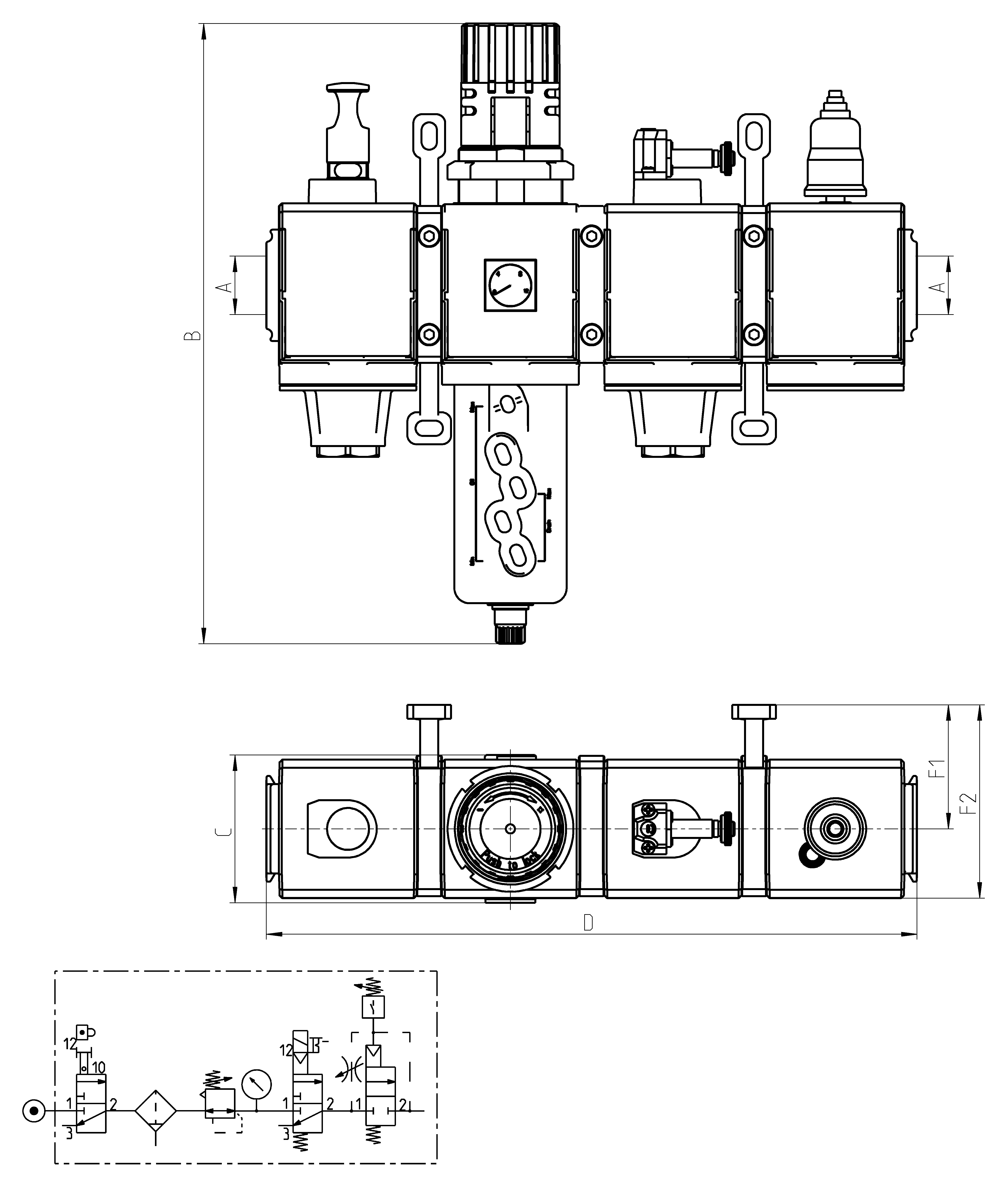
| Mod. | A | B | C | D | F1 | F2 |
| MX2-3/8-000010 | G3/8 | 289 | 74,5 | 280 | 70 | 104,5 |
| MX2-1/2-000010 | G1/2 | 289 | 74,5 | 280 | 70 | 104,5 |
| MX2-3/4-000010 | G3/4 | 289 | 74,5 | 280 | 70 | 104,5 |
| MX3-3/4-000010 | G3/4 | 345 | 81 | 358 | 68 | 106 |
| MX3-1-000010 | G1 | 345 | 81 | 358 | 68 | 106 |
