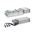
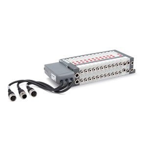
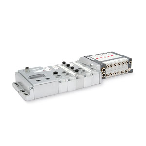
Ventilinseln Multipol, Feldbus-Version
Serie F
Modularität 1, 2 bis 24 Ventile
Ventile 2x 2/2-, 2x 3/2-, 5/2-, 5/3-Wege, PROFIBUS-DP, DeviceNet, CANopen, EtherNet/IP, EtherCAT, PROFINET
Ventile 2x 2/2-, 2x 3/2-, 5/2-, 5/3-Wege, PROFIBUS-DP, DeviceNet, CANopen, EtherNet/IP, EtherCAT, PROFINET
Die Multipol-Ventilinsel Serie F kann auch mit den Elementen des Feldbus-Systems und damit mit den unterschiedlichen Protokollen der Serie CX eingesetzt werden. Es gibt auch die Möglichkeit, eine normale Multipol-Insel durch einen SUB-D Adapter oder aber einen integrierten Feldbus-Knoten zu verwenden. Durch die Modularität 1 der Serie F können maximal 24 Vorsteuerventile für 24 Ventilpositionen auch als Bus-Version verwendet werden.
Die Verwendung von Kunststoffen zur Realisierung dieser Serie ermöglicht eine Ventilinsel in kompakter Größe, hohem Durchfluss und geringem Gewicht.
Die kompakte Bauform, flexible Montage und die vielfache Auswahl an Ventilfunktionen machen die Serie F zu einem besonders innovativen Produkt, geeignet für die vielfältigsten Anwendungen.
Benutzerhandbuch, Konfigurationsprogramm unter http://catalogue.camozzi.com sowie auf dem QR-Code des Produktetiketts.
Series
there are no salable codes online
If you have entered Filters, try changing them or look in the "Configurator" tab


addtocart.popup.message.success
Die angeforderte Menge ist teilweise bestätigt.
Das Produkt {0} befindet sich bereits mit der Menge {1} in Ihrem Warenkorb. Sie können die Menge auf der Seite "Warenkorb" aktualisieren.
Das Produkt ist nicht aktiv.
Das Produkt konnte nicht in den Warenkorb gelegt werden, da es nicht vorrätig ist.
Die Menge muss größer Null sein.
Die zulässige Mindestmenge für das Produkt {0} ist {1}.
Die maximal zulässige Menge für Produkt {0} ist {1}.
Die Verpackungseinheit für Produkt {0} ist {1}.
Es ist nicht möglich, das Produkt mit dem Code {0} in den Warenkorb zu legen.
Es ist ein Fehler aufgetreten, bitte versuchen Sie es später noch einmal oder wenden Sie sich an den Kundenservice.
| PNEUMATISCHE KENNGRÖSSEN | |
| Bauart | Schieberventil, weichgedichtet |
| Funktion | 5/2 monostabil und bistabil 5/3-Wege, Mitte geschlossen 2x2/2 NO 2x2/2 NC 1x2/2 NC + 1x2/2 NO 2x3/2 NO 2x3/2 NC 1x3/2 NC + 1x3/2 NO |
| Werkstoffe | Schieber Aluminium und HNBR Dichtungen - Restliche Dichtungen NBR - Führungskäfige Messing - Körper und Endplatten Kunststoff |
| Anschlüsse | Anschlüsse 2 und 4, Baubreite 1 (12 mm) = Schlauch Ø 4 mm; Ø 6 mm Anschlüsse 2 und 4, Baubreite 2 (14 mm) = Schlauch Ø 4 mm; Ø 6 mm; Ø 8 mm P-Versorgung, Baubreite 1 und 2 = Schlauch Ø 8 mm; Ø 10 mm Vorsteuerung 12/14, Baubreite 1 und 2 = Schlauch Ø 6 mm Entlüftung 3/5, Baubreite 1 und 2 = Schlauch Ø 8 mm; Ø 10 mm Entlüftung 82/84, Baubreite 1 und 2 = Schlauch Ø 6 mm |
| Temperaturbereich | 0°C ÷ 50 °C |
| Luftqualität | Gefilterte, ölfreie Luft Klasse 6.4.4 / ISO 8573-1:2010. Bei Schmierung Öle mit Viskosität max. 32 Cst verwenden sowie externe Vorsteuerung. |
| Baubreite Ventile | 12 mm 14 mm |
| Betriebsdruck | - 0,9 ÷ 10 bar |
| Interne Vorsteuerung | 3 ÷ 7 bar 4.5 ÷ 7 bar (für Ventilfunktionen 2x2/2- und 2x3/2-Wege bei Betriebsdruck >6 bar) |
| Durchfluss | 250 Nl/min (12 mm) 500 Nl/min (14 mm) |
| Einbaulage | Beliebig |
| Einschaltdauer | ED 100% |
| Schutzart (entsprechend EN 60529) | IP40 (mit montiertem Anschlusskabel) |
| ELEKTRISCHE KENNGRÖSSEN - MULTIPOL | |
| Spannung Max. Anzahl von Spulen Max. Anzahl von Ventilpositionen SUB-D Anschluss Leistungsaufnahme max. |
24 V DC +/- 10% 24 24 (monostabil) SUB-D 25-polig 0.8 A |
| ELEKTRISCHE KENNGRÖSSEN - FELDBUS | |
| Allgemeine Kenngrößen Stromaufnahme max. Versorgungsspannung Max. Anzahl von Spulen |
Siehe Serie CX I/O analog + digital 3A 24 V DC +/- 10% Für 24 Ventilpositionen (monostabil) |
MODELLBEZEICHNUNG - EINZELVENTILE (ERSATZTEIL), ZWISCHENPLATTEN UND ENDPLATTEN (ZUBEHÖR)
| FP2V-MQR | F | P | 2 | V | - | M | Q | R | FA2T-S | F | A | 2 | T | - | S |
|
CODING EXAMPLE OF A SINGLE SOLENOID VALVE |
CODING EXAMPLE OF INTERMEDIATE PLATES |
||
| FP2V-MQR | FP2V-WQ | ||
| F | Series | F | Series |
| P |
Type: P = pneumatic |
P |
Type: P = pneumatic |
| 2 |
Size: 1 = 12 mm 2 = 14 mm |
2 |
Size: 1 = 12 mm 2 = 14 mm |
| V | Solenoid valve or additional plate | V | Solenoid valve or additional plate |
| M |
Type of function: M = 5/2 monostable D = 5/2 monostable with bistable board B = 5/2 bistable C = 2 x 3/2 NC A = 2 x 3/2 NO G = 3/2 NC + 3/2 NO E = 2 x 2/2 NC F = 2 x 2/2 NO I = 2/2 NC + 2/2 NO V = 5/3 CC |
W |
Type of function: L = free position W = free position with bistable board Z = free position with monostable board X = supplementary power supply and exhaust T = separated power supply and exhaust U = separated power supply and supplementary exhaust K = supplementary power supply and separated exhaust |
| Q |
Cartridges for solenoid valves: Q = Ø4 R = Ø6 S = Ø8 (not for Size 1) |
Q |
Cartridges for plates: Q = Ø4 R = Ø6 S = Ø8 (not for Size 1) L = free position (no cartridges) W = free position with bistable board (no cartridges) Z = free position with monostable board (no cartridges) |
| R |
Type of manual override: R = push and turn (bistable) P = pressure (monostable) |
||
|
|
|||
|
CODING EXAMPLE OF A LEFT TERMINAL |
CODING EXAMPLE OF A RIGHT TERMINAL |
||
| FA2T-S | FA2T-AR | ||
| F | Series | F | Series |
| A | Accessory | A | Accessory |
| 2 |
Size: 1 = 12 mm 2 = 14 mm |
2 |
Size: 1 = 12 mm 2 = 14 mm |
| T |
Type of accessory: T = terminal |
T |
Type of accessory: T = terminal |
| S |
Cartridges: = no cartridge S = Ø8 T = Ø10 |
A |
Type of servo-pilot: A = internal B = external |
| R |
Cartridges: R = Ø6 |
| F | P | 2 | V | - | M | Q | R |
| F | SERIE |
| P |
Typ P = pneumatisch |
| 2 |
Baubreite 1 = 12 mm 2 = 14 mm |
| V | Magnetventil oder Zwischenplatte |
| M |
Funktion M = 5/2 monostable D = 5/2 monostable with bistable board B = 5/2 bistable C = 2 x 3/2 NC A = 2 x 3/2 NO G = 3/2 NC + 3/2 NO E = 2 x 2/2 NC F = 2 x 2/2 NO I = 2/2 NC + 2/2 NO V = 5/3 CC |
| Q |
Steckanschlüsse Q = Ø 4 mm R = Ø 6 mm S = Ø 8 mm (nur baubreite 2) |
| R |
Art der Handhilfsbetätigung R = bistabil P = monostabil |
 Schweiz


 Katalog herunterladen


