 France


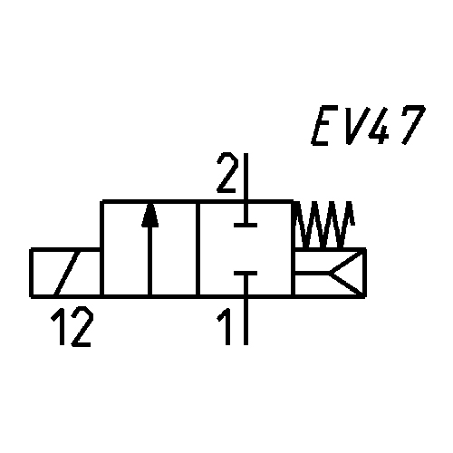
Solenoid valve - with linked diaphragm - 2/2 NC
Series CFB
The diaphragm which is linked to the mobile plunger is a good arrangement between high fluid flow rates and working pressures (zero pressures as well).
Ports: from G3/8 to G1.
The standard diaphragm is supplied in FKM.
Ports: from G3/8 to G1.
The standard diaphragm is supplied in FKM.
 Download catalogue
Series
there are no salable codes online
If you have entered Filters, try changing them or look in the "Configurator" tab


Quantity added:
addtocart.popup.message.success
The requested quantity is partially confirmed
Product {0} is already in your cart with quantity {1}. You can update the quantity from cart page.
Product is not active
The product could not be added to the cart due to insufficient stock
Quantity must be greater than zero
Min allowed quantity for product {0} is {1}
Max allowed quantity for product {0} is {1}
Pack size for product {0} is {1}
It is not possible to add the product with code {0} to this cart
An error occurred, please try again later or contact customer support

Full screen

Quantity added:
addtocart.popup.message.success
The requested quantity is partially confirmed
Product {0} is already in your cart with quantity {1}. You can update the quantity from cart page.
Product is not active
The product could not be added to the cart due to insufficient stock
Quantity must be greater than zero
Min allowed quantity for product {0} is {1}
Max allowed quantity for product {0} is {1}
Pack size for product {0} is {1}
It is not possible to add the product with code {0} to this cart
An error occurred, please try again later or contact customer support
Coding example
| CFB | - | A | 1 | 3 | L | - | R | 1 | - | B7 | E |
| CFB | SERIES |
| A |
OPERATION A = indirect B = direct with linked diaphragm D = direct E = indirect with coil for heavy-duty applications |
| 1 |
NUMBER OF WAYS - POSITIONS 1 = 2/2-way - NO 2 = 2/2-way - NC 3 = 3/2-way - NC |
| 3 |
CONNECTIONS 1 = G1/8 2 = G1/4 3 = G3/8 4 = G1/2 5 = G3/4 6 = G1 7 = G1 1/4 8 = G1 1/2 9 = G2 |
| L |
ORIFICE DIAMETER A = 1.4 mm B = 2 mm C = 2.5 mm D = 2.8 mm F = 4 mm G = 6 mm J = 8 mm L = 11.5 mm M = 13 mm N = 13.5 mm P = 18 mm R = 26 mm T = 32 mm X = 45 mm Z = 50 mm |
| R |
SEALS MATERIAL R = NBR W = FKM E = EPDM (on demand) |
| 1 |
BODY MATERIAL 1 = brass 2 = alimentary anti-limestone nickel-plated brass for high temperatures (on demand) 3 = alimentary nickel-plated brass (on demand) |
| B7 |
SOLENOID DIMENSION B7 = 22 mm B8 = 30 mm B9 = 36 mm |
| E |
SOLENOID VOLTAGE B = 24 V AC 50 Hz D = 110 V AC 50/60 Hz E = 230 V AC 50/60 Hz 2 = 12 V DC 3 = 24 V DC |
Series CFB solenoid valve - with linked diaphragm - 2/2 NC
* = choose the suitable solenoid according to the TABLE FOR THE COUPLING BETWEEN SOLENOID AND VALVES
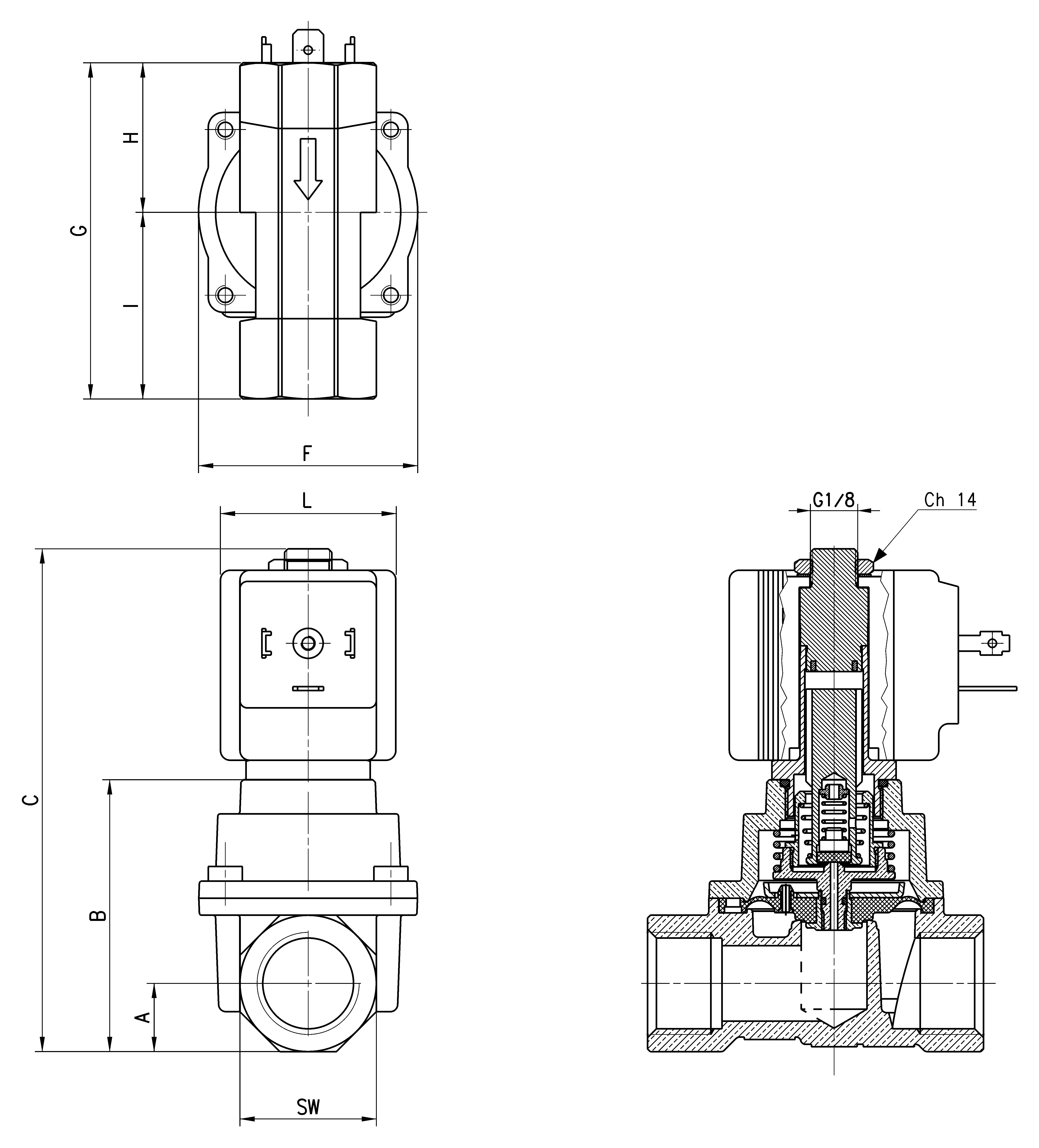
| Mod. | Function | Ports | Ø Orifice (mm) | Kv (m³/h) | Pressure min÷max (bar) | A | B | C | F | G | H | I | L | SW |
| CFB-B23L-W1-* | 2/2 NC | G3/8 | 11.5 | 2.1 | 0 ÷ 15 [ AC ] - 0 ÷ 8 [ DC ] | 14 | 55.8 | 103.2 | 45 | 64 | 28.2 | 35.8 | 36 | 28 |
| CFB-B24N-W1-* | 2/2 NC | G1/2 | 13.5 | 2.5 | 0 ÷ 15 [ AC ] - 0 ÷ 8 [ DC ] | 14 | 55.8 | 103.2 | 45 | 69 | 30.7 | 38.3 | 36 | 28 |
| CFB-B25P-W1-* | 2/2 NC | G3/4 | 18 | 5 | 0 ÷ 15 [ AC ] - 0 ÷ 5 [ DC ] | 21 | 72 | 119.4 | 71 | 93 | 43.5 | 49.5 | 36 | 42 |
| CFB-B26R-W1-* | 2/2 NC | G1 | 26 | 8 | 0 ÷ 15 [ AC ] - 0 ÷ 5 [ DC ] | 21 | 72 | 119.4 | 71 | 93 | 43.5 | 49.5 | 36 | 42 |
