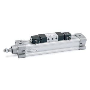
Cylinders - round tube, double-acting
Series 63
Versions: 63MT2... 63LT2... and 63VT2...
Series
Accessories
Cylinder ser. 63 tube - 63MT2C032A0025
Cylinder ser. 63 tube - 63MT2C040A0025
Cylinder s. 63 tube - 63MT2C050A0025
Cylinder ser. 63 tube - 63MT2C063A0025
Cylinder ser. 63 tube - 63MT2C032A0050
Cylinder ser. 63 tube - 63MT2C040A0050
Cylinder ser. 63 tube - 63MT2C050A0050
Cylinder ser. 63 tube - 63MT2C063A0050
Cylinder ser. 63 tube - 63MT2C080A0050
Cylinder s. 63 tube - 63MT2C100A0050
Cylinder s.63 tube - 63MT2C125A0050
Cylinder s. 63 tube - 63MT2C040A0060
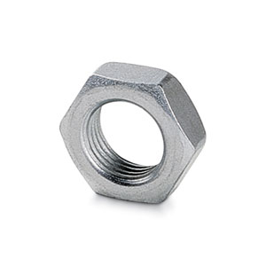
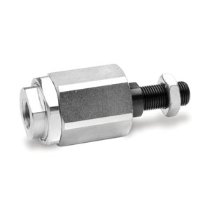
Rod end alignment coupler - GK-50-63
Rod end algnmnt cplr m20x1,5 - GK-80-100
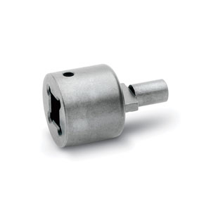
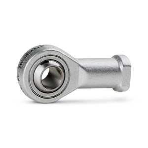
Piston rod socket joint - GY-50-63
Piston rod socket joint - GY-80-100
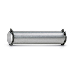
Clevis pin - S-50
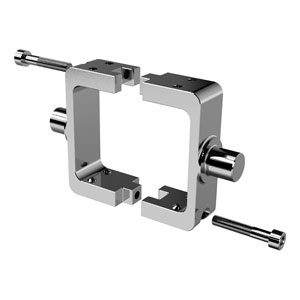
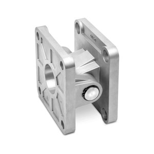
Rear trunnion (ball joint) - R-41-100
Rear trunnion - R-41-125
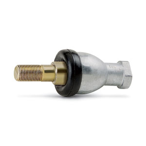
Compensator joint m10x1,25 - GKF-25-32
Coupler m12x1,25 - GKF-40
Compensator joint m16x1,50 - GKF-50-63
Compensator joints m20x1,50 - GKF-80-100
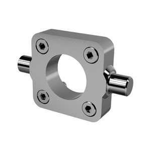
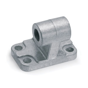
Front/rear trunnion (female) - C-H-41-100
Front/rear trunnion (female) - C-H-41-125
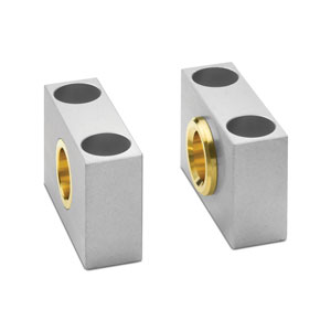
Rear trunnion (female) - C-H-41-63
Front/rear trunnion (female) - C-H-41-80
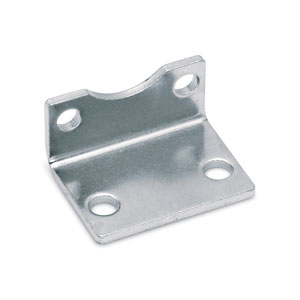
Foot mount - B-41-100
Foot mount - B-41-125
Foot mount - B-41-32
Foot mount - B-41-40
Foot mount - B-41-50
Foot mount - B-41-63
Foot mount - B-41-80
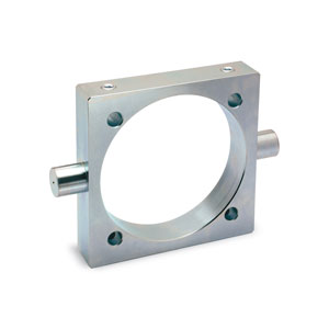
Front/rear flange - D-E-31-32
Front/rear flange - D-E-41-100
Front/rear flange - D-E-41-125
Front/rear flange - D-E-41-40
Front/rear flange - D-E-41-50
Front/rear flange - D-E-41-63
Front/rear flange - D-E-41-80
Center trunnion - FN-100
Center trunnion - FN-125
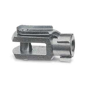
Rod clevis - G-25-32
Rod clevis - G-40
Rod clevis - G-41-125
Rod clevis - G-50-63
Rod clevis - G-80-100
Kit actuator - F-63-100
Kit actuator - F-63-125
Kit actuator - F-63-32
Kit actuator - F-63-40
Kit actuator - F-63-50
Kit actuator - F-63-63
Kit actuator - F-63-80
Counter bracket for cntr trn - BF-100-125
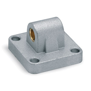
Rear trunnion (male) - L-41-100
Rear trunnion (male) - L-41-125
Rear trunnion (male) - L-41-32
Rear trunnion (male) - L-41-40
Rear trunnion (male) - L-41-50
Rear trunnion (male) - L-41-63
Rear trunnion (male) - L-41-80
Accessory kit movement _ - DC-63-100
Accessory kit movement _ - DC-63-125
Accessory kit movement _ - DC-63-32
Accessory kit movement _ - DC-63-40
Accessory kit movement _ - DC-63-50
Accessory kit movement _ - DC-63-63
Accessory kit movement _ - DC-63-80
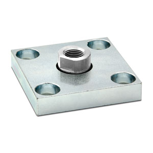
Mounting plate kit - PCV-62-K3
Mounting plate kit - PCV-62-K4
Mounting plate kit - PCV-62-K8
Mounting plate kit - PCV-62-KEN


addtocart.popup.message.success
The requested quantity is partially confirmed
Product {0} is already in your cart with quantity {1}. You can update the quantity from cart page.
Product is not active
The product could not be added to the cart due to insufficient stock
Quantity must be greater than zero
Min allowed quantity for product {0} is {1}
Max allowed quantity for product {0} is {1}
Pack size for product {0} is {1}
It is not possible to add the product with code {0} to this cart
An error occurred, please try again later or contact customer support
CODING EXAMPLE
* Only for low friction
| 63 | M | P | 2 | C | 050 | A | 0200 | W |
| 63 | SERIES | |
| M |
VERSION M = standard, magnetic V = uniform movement (no stick slip), magnetic L = low friction, magnetic |
|
| P |
CONSTRUCTION T = round tube P = profile |
|
| 2 |
OPERATION 1 = single-acting, front spring 2 = double-acting 6 = double-acting, through-rod 7 = single-acting, through-rod 9 = single-acting, rear spring |
PNEUMATIC SYMBOLS CS07/CS18 CD08 - CD09 - CD10 - CD11 CD13 CS11 CS14/CS17 |
| C |
CUSHIONING N = no cushioning (mechanical endstops) C = cushioning on both sides F = front cushioning R = rear cushioning |
PNEUMATIC SYMBOLS CD08 CD09/CD13 CD11 CD10 |
| 050 |
BORE 032 = 32 mm 040 = 40 mm 050 = 50 mm 063 = 63 mm |
080 = 80 mm 100 = 100 mm 125 = 125 mm |
| A |
CONSTRUCTIVE TYPE A = standard with rod nut RL = cylinder with rod lock |
DC = back to back cylinder with DC accessory [X1/X2] TR = back to back cylinder for round tube [X1/X2] F = cylinder with centre trunnion |
| 0200 |
STROKE = standard N = tandem / = more positions X1/X2 [X1<X2] |
|
| W |
TEMPERATURE RANGE = standard (-20°/+80°) W = high temperatures (150°C) |
Z = low temperatures (-40°C) Y = low temperatures (-50°C) |
|
RESISTANCE TO CORROSION = standard C1 = rod nut AISI 304 stainless steel, rod AISI 304 stainless steel C2 = end cap treated screws (profile) or AISI 303 tie-rods and AISI 420B tie-rods (round tube) |
C3 = C2 + AISI 316 rod nut, AISI 316 rod C4 = C1 + C2 C5 = C3 + end caps with triple protection |
|
|
ROD VARIATIONS = standard (male rod thread) F = female rod thread K = end caps with Kanigen treatment (only for corrosion resistance category C2, C3 and C4) L = without rod seal (rear air inlet only)* V = FKM rod seal R = NBR rod seal U = unlubricated operation |
H = hydrolytic environment A = use in food and other frequent washdown applications G = dry and dusty environments (with brass rod scraper and chrome-plated stainless steel AISI 420B rod) B = cylinder with NBR bellow rod protection (_ _ _) = extended rod _ _ _ mm |
|
|
OTHER P = cylinder with RAL 7035 polyurethane coating |
||
|
CERTIFICATIONS EX = ATEX |
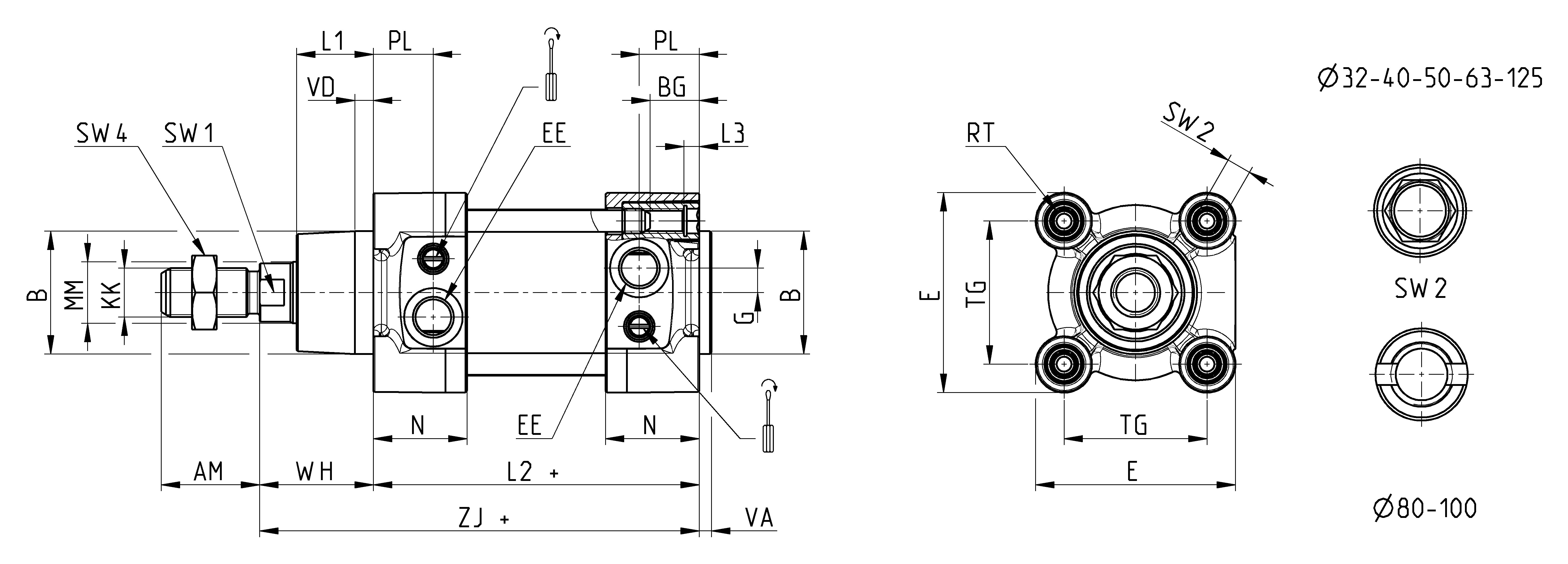
| Ø | ØMM | KK | ØB | PL | L1 | AM | VA | EE | WH | L2 + | L3 | ZJ + | VD | N | BG | RT | G | TG | E | SW1 | SW2 | SW4 | front/rear cushion stroke |
| 32 | 12 | M10x1,25 | 30 | 18,5 | 18 | 22 | 4 | G1/8 | 26 | 94 | 5 | 120 | 5 | 27 | 16 | M6 | 5 | 32,5 | 47 | 10 | 6 | 17 | 17 |
| 40 | 16 | M12x1,25 | 35 | 19 | 21 | 24 | 4 | G1/4 | 30 | 105 | 5 | 135 | 5 | 30 | 16 | M6 | 5 | 38 | 55 | 13 | 6 | 19 | 18 |
| 50 | 20 | M16x1,5 | 40 | 19,5 | 25 | 32 | 4 | G1/4 | 37 | 106 | 5 | 143 | 6 | 30,5 | 16 | M8 | 8 | 46,5 | 65 | 17 | 8 | 24 | 20 |
| 63 | 20 | M16x1,5 | 45 | 24 | 26 | 32 | 4 | G3/8 | 37 | 121 | 5 | 158 | 6 | 37,5 | 16 | M8 | 8 | 56,5 | 75 | 17 | 8 | 24 | 22 |
| 80 | 25 | M20x1,5 | 45 | 23,5 | 30 | 40 | 4 | G3/8 | 46 | 128 | 0 | 174 | 7 | 37 | 19 | M10 | 8 | 72 | 93 | 22 | * | 30 | 25 |
| 100 | 25 | M20x1,5 | 55 | 24 | 35 | 40 | 4 | G1/2 | 51 | 138 | 0 | 189 | 7 | 39,5 | 19,5 | M10 | 8 | 89 | 110 | 22 | * | 30 | 26 |
| 125 | 32 | M27x2 | 60 | 28 | 42 | 54 | 6 | G1/2 | 65 | 160 | 6 | 225 | 8 | 44 | 23 | M12 | 10,5 | 110 | 135 | 27 | 12 | 41 | 33 |
1-16/31 results
 Greece


 Download catalogue
.jpg)
.jpg)
.jpg)
.jpg)
.jpg)
