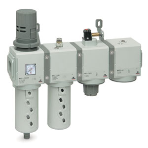
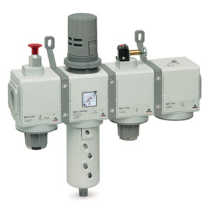
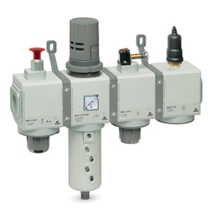
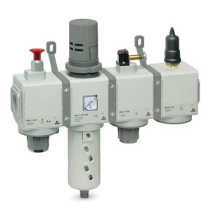
过滤器、减压器、油雾器组合件
MX 系列
规格 MX2, MX3
接口 G3/8, G1/2, G3/4(MX2)- G3/4, G1(MX3)
接口 G3/8, G1/2, G3/4(MX2)- G3/4, G1(MX3)
Series MX FRL can be easily assembled through rapid clamps which allow the connection among single components creating an unlimited number of compositions.
The FRL groups Series MX are also available in the already mounted version (with a single code).
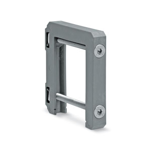
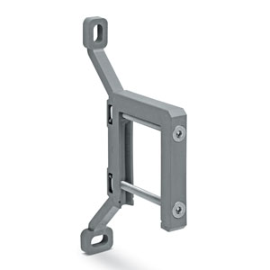
The use of three different types of rapid clamps (standard, with wall fixing screws or with brackets) allows an easy mounting of the assembled groups and to carry out maintenance operations on the single components with no need to disassemble the group.
Series
Accessories
there are no salable codes online
If you have entered Filters, try changing them or look in the "Configurator" tab
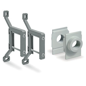
In-out flanges kit - MX2-3/4-FL
In-out flanges kit - MX2-3/8-FL
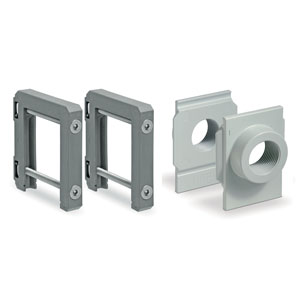
Rap.clamps+flanges kit s. mx - MX2-1/2-JJ
Mx系列端部法兰组件 - MX2-1/2-KK
Mx系列端部法兰组件 - MX3-1-KK


addtocart.popup.message.success
请求的数量已部分确认
产品 {0} 已在您的购物车中,数量为 {1} 。您可以从购物车页面更新数量
产品未激活
由于库存不足,无法将此产品添加到购物车
数量必须大于零
产品 {0} 允许的最小数量为 {1}
产品 {0} 允许的最大数量为 {1}
产品 {0} 的包装尺寸是 {1}
无法将代码 {0} 的产品添加到此购物车
出现错误,请稍后重试或联系客户支持
| 结构形式 | 模块型设计,紧凑型 |
| 材料 | 见各相关元件的材料一览 |
| 接口 | MX2:G3/8 - G1/2 - G3/4 MX3:G3/4 - G1 |
| 安装方式 | 垂直放置 附壁式安装 面板式安装 |
| 工作温度 | -5°C ÷ 50°C:最大工作压力可达 16 bar(介质的露点应不低于 2°C) -5°C ÷ 60°C:最大工作压力可达 10 bar(介质的露点应不低于 2°C) |
MX 系列过滤器、减压器和油雾器组合件代号
| MX | 2 | - | 1 /2 | - | V01 | X | F00 | X | V1841AB | - | KK | - | LH |
| MX | SERIES | |||
| 2 | (1) |
SIZES 2 = G3/8 - G1/2 - G3/4 3 = G3/4 - G1 |
||
| 1 /2 | (2) |
IN / OUT THREADS 3/8 = G3/8 1/2 = G1/2 3/4 = G3/4 1 = G1 |
||
| V01 | (3) |
MODULE + [+] (to configure the modules, see the single components pages): |
F…= Filter FC... = Coalescing filter FCA... = Activated carbons filte R... = Pressure regulator L... = Lubricator FR... = Filter-Regulator |
V... = Lockable isolation valve V16..; V17..; V18..; V19.. = Machinery Directive solenoid valves (use version without mounting accessories) (only for MX2) AV... = Soft start valve B... = Take-off block (MX2: G1/2 only - MX3: G1 only) |
| [ * ] |
The following ACCESSORIES can be added after every single module: REGULATOR AND FILTER-REGULATOR MX2 +A12 = SWCN-P10-P3-2 (Electronic pressure switch) +A13 = SWCN-P10-P4-2 (Electronic pressure switch) +A14 = SWCN-P10-P4-M (Electronic pressure switch) +A52 = PG010-PB-1/8 (Pressure gauge) +A53 = PG010-PB-1/8-2 (Pressure gauge) +A54 = PG010-PB-1/8-M (Pressure gauge +A55 = M053-P04 (Pressure gauge) +A56 = M053-P06 (Pressure gauge) +A57 = M053-P10 (Pressure gauge) +A58 = M063-P12 (Pressure gauge) |
REGULATOR AND FILTER-REGULATOR MX3 +A15 = SWCN-P10-P3-2 (Electronic pressure switch) +A16 = SWCN-P10-P4-2 (Electronic pressure switch) +A17 = SWCN-P10-P4-M (Electronic pressure switch) +A59 = M063-P04 (Pressure gauge) +A60 = M063-P06 (Pressure gauge) +A61 = M063-P12 (Pressure gauge) +A62 = PG010-PB-1/4 (Pressure gauge) +A63 = PG010-PB-1/8-2 (Pressure gauge) +A64 = PG010-PB-1/8-M (Pressure gauge) |
||
|
LOCKABLE ISOLATION VALVE MX2 +A30 = 2901 1/2’’ (Silencier) +A31 = 2921 1/2’’ (Silencier) +A32 = 2931 1/2’’ (Silencier) +A33 = 2928 1/2’’ (Silencier) |
LOCKABLE ISOLATION VALVE MX3 +A34 = 2901 3/4’’ (Silencier) +A35 = 2921 3/4’’ (Silencier) +A36 = 2931 3/4’’ (Silencier) +A37 = 2928 3/4’’ (Silencier) |
|||
|
SOFT START VALVE +A00 = PM11-NA (Pressure switch, normally open) +A01 = PM11-NC (Pressure switch, normally closed) +A04 = PM11-SC (Pressure switch) +A05 = PM681-1 (Pressure switch) +A18 = PM681-3 (Pressure switch) |
||||
|
TAKE-OFF BLOCK MX2 +A11 = PM681-1 (Pressure switch) +A24 = PM681-3 (Pressure switch +A08 = PM11-NA (normally open pressure switch) with fitting for fixing to the module +A09 = PM11-NC (normally closed pressure switch) with fitting for fixing to the module +A03 = PM11-SC with fitting for fixing to the module Example: MX2-3/8-V01+A32XF00-KK-LH |
TAKE-OFF BLOCK MX3 +A06 = PM11-NA (normally open pressure switch) with fitting for fixing to the module +A07 = PM11-NC (normally closed pressure switch) with fitting for fixing to the module +A10 = PM681-1 (Pressure switch) +A25 = PM681+3 (Pressure switch) +A02 = PM11-SC with fitting for fixing to the module Example: MX3-3/4-V01+A36XF00-KK-LH |
ISOLATION VALVE MX2 / MX3 +A40 = U7H Coil UL (12V DC) +A41 = U77 Coil UL (24V DC) +A42 = U79 Coil UL (48V DC) +A43 = U7K Coil UL (110V AC) +A44 = U7J Coil UL (230V AC) +A45 = G7H Coil (12V DC) +A46 = G77 Coil (24V DC) +A47 = G79 Coil (48V DC) +A48 = G7K Coil (110V AC) +A49 = G7J Coil (230V AC) |
||
| X | (4) |
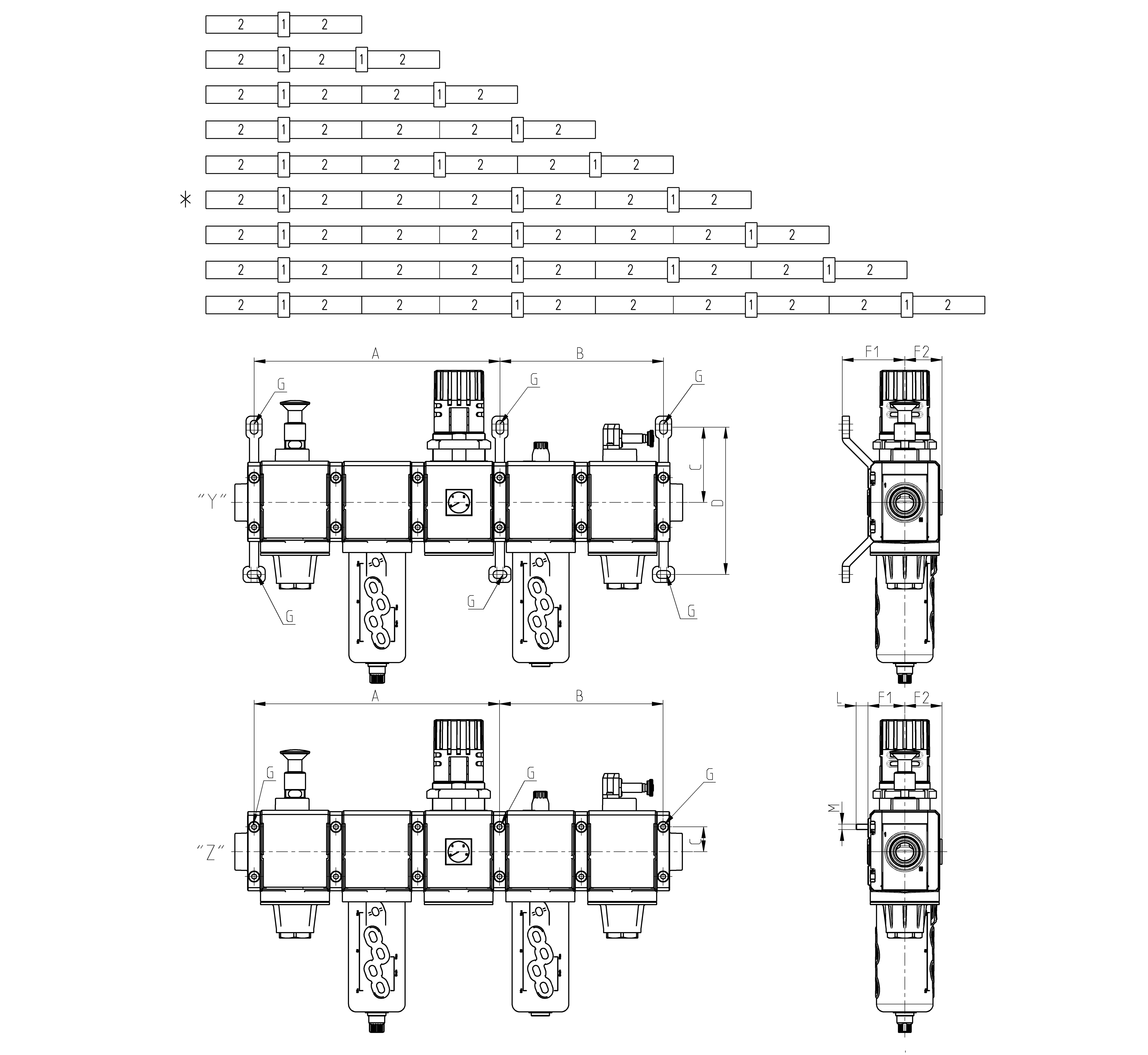
MODULES CONNECTION (according to the positioning scheme on the following page): X = Rapid clamp kit Z = Rapid clamp kit with wall fixing screw Y = Rapid clamp kit with wall fixing brackets |
||
| F00 | (5) + [ * ] | see MODULE (3) | ||
| X | (4) | |||
| V1841AB | (5) + [ * ] | see FORM (3) - if other forms are present | ||
| KK | (6) |
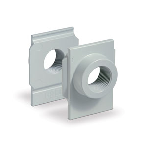
TERMINAL CONNECTIONS + [ ** ] = no terminal connection HH = n° 1 rapid clamp kit with flanges (IN / OUT) JJ = n° 1 rapid clamp kit with wall fixing screws + flanges (IN / OUT) KK = n° 1 rapid clamp kit with wall fixing brackets + flanges (IN / OUT) |
||
| [ ** ] |
WALL CONNECTION: REGULATOR and FILTER-REGULATOR S = Bracket (only with clamps mod. X o HH) Codes examples: MX3-1-R..XV..-S ; MX3-1-R..XV..-HSH |
|||
| LH | (7) |
FLOW DIRECTION: = from left to right (standard) LH = from right to left |
||
| (4) + (5) + [ * ] | REPEATABLE COMBINATION for a “n” number of times |
Coding example
| MX | 2 | - | 3/8 | - | 000001 |
| MX | 系列 |
| 2 |
SIZE 2 = G3/8 - G1/2 - G3/4 3 = G3/4 - G1 |
| 3/8 |
PORTS: 3/8 = G3/8 1/2 = G1/2 3/4 = G3/4 1 = G1 |
| 000001 |
组合件代号: 000001 = F10 + R004 + L00 000002 = FR1004 + L00 000003 = V01 + FR1004 + L00 000004 = V01 + FR1004 000005 = FR1004 + V16 + AV 000006 = FR1004 + L00 + V16 + AV 000007 = V01 + FR1004 + V16 + AV 000008 = V01 + FR1004 + L00 + V16 + AV + 压力开关 NO 000009 = V01 + FR1004 + L00 + V16 + AV + 压力开关 NC 000010 = V01 + FR1004 + V16 + AV + 压力开关 NO 000011 = V01 + FR1004 + V16 + AV + 压力开关 NC 000012 = F13 + FC03 |
|
WARNING: IN THE PRESENCE OF METAL PIPES, THE USE OF CONNECTION FLANGES MAKE THE MAINTENANCE ACTIVITIES EASIER. INITIALLY PROCEED BY ASSEMBLING THE PIPES ON THE FLANGES, THEN FIX THE TREATMENT UNIT TO THE WALL THROUGH THE PROPER FIXING BRACKETS |
 马来西亚
马来西亚


 样本下载
样本下载