Series
Accessories
there are no salable codes online
If you have entered Filters, try changing them or look in the "Configurator" tab
there are no salable codes online
Look in the "Accessory" tab for the Configurator


addtocart.popup.message.success
The requested quantity is partially confirmed
Product {0} is already in your cart with quantity {1}. You can update the quantity from cart page.
Product is not active
The product could not be added to the cart due to insufficient stock
Quantity must be greater than zero
Min allowed quantity for product {0} is {1}
Max allowed quantity for product {0} is {1}
Pack size for product {0} is {1}
It is not possible to add the product with code {0} to this cart
An error occurred, please try again later or contact customer support
CODING EXAMPLE
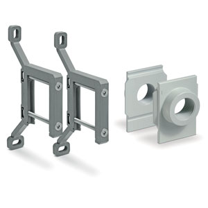
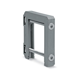
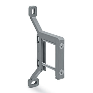
For the assembly of a single component with fixing flanges or wall-mounting, see the section "FRL Series MX Assembled"
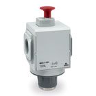
| MX | 2 | 3/8 | V | 01 | LH |
| MX | SERIES |
| 2 |
SIZE: 2 = G3/8 - G1/2 - G3/4 3 = G3/4 - G1 |
| 3/8 |
PORT: 3/8 = G3/8 1/2 = G1/2 3/4 = G3/4 1 = G1 |
| V | 3/2-WAY VALVE |
| 01 |
DESIGN TYPE: 01 = lockable manual control 16 = electro-pneumatic control 17 = servo-pilot control 36 = pneumatic control |
| LH |
FLOW DIRECTION: = from left to right (standard) LH = from right to left |
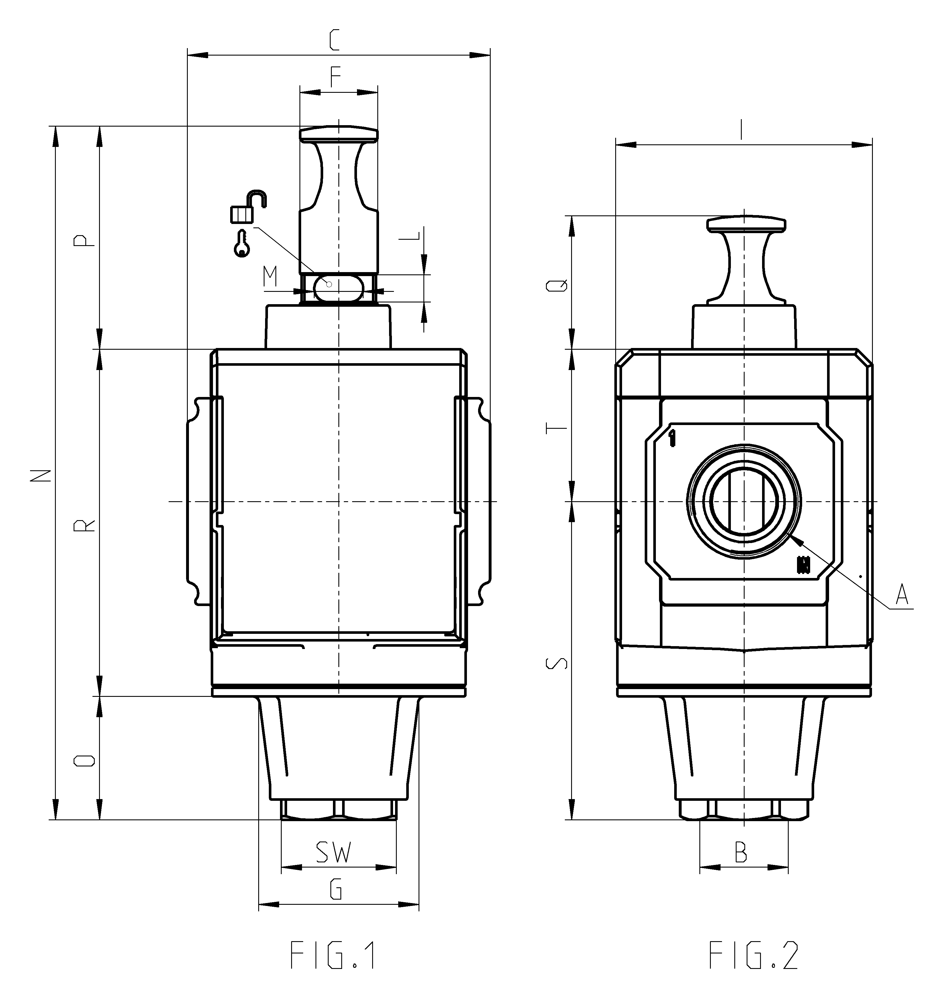
| Mod. | A | B | C | F | G | I | L | M | N | O | P | Q | R | S | SW | T | Weight (kg) |
| MX2-3/8-V01 | G3/8 | G 1/2 | 70 | 26 | 34,5 | 68 | 9 | 8 | 152 | 13 | 51 | 31 | 88 | 63,5 | 27 | 37,5 | 0.5 |
| MX2-1/2-V01 | G 1/2 | G 1/2 | 70 | 26 | 34,5 | 68 | 9 | 8 | 152 | 13 | 51 | 31 | 88 | 63,5 | 27 | 37,5 | 0.5 |
| MX2-3/4-V01 | G3/4 | G 1/2 | 70 | 26 | 34,5 | 68 | 9 | 8 | 152 | 13 | 51 | 31 | 88 | 63,5 | 27 | 37,5 | 0.5 |
| MX3-3/4-V01 | G3/4 | G3/4 | 89,5 | 32 | 48 | 76 | 8 | 14,5 | 205,5 | 37 | 66,5 | 40 | 102 | 94,5 | 34 | 44,5 | 0.9 |
| MX3-1-V01 | G1 | G3/4 | 89,5 | 32 | 48 | 76 | 8 | 14,5 | 205,5 | 37 | 66,5 | 40 | 102 | 94,5 | 34 | 44,5 | 0.9 |
 United States


 Download catalogue
