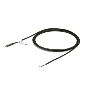
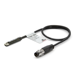
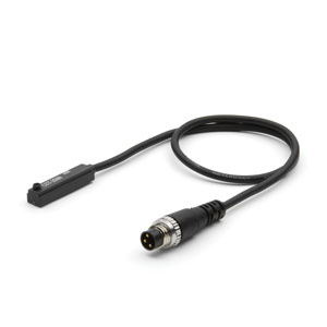
Compact magnetic cylinders - through-rod Mod. 31F and 31M - through-rod
Series 31
Series
Accessories
Compact cylinders - 31F3A012A005
Compact cylinders - 31F3A012A010
Compact cylinders - 31F3A012A015
Compact cylinders - 31F3A012A020
Compact cylinders - 31F3A012A025
Compact cylinders - 31F3A012A030
Compact cylinders - 31F3A012A040
Compact cylinder ser. 31 - 31F3A016A005
Compact cylinder ser. 31 - 31F3A016A005EX
Compact cylinders - 31F3A016A010
Compact cylinder ser. 31 - 31F3A016A015
Compact cylinders - 31F3A016A020
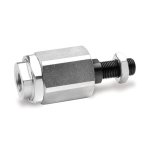
Rod end alignment coupler - GK-50-63
Rod end algnmnt cplr m20x1,5 - GK-80-100
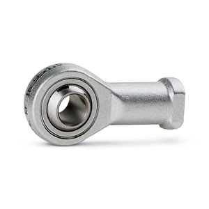
Piston rod socket joint - GY-12-16
Piston rod socket joint - GY-50-63
Piston rod socket joint - GY-80-100
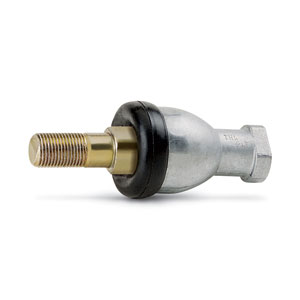
Compensator joint m10x1,25 - GKF-25-32
Coupler m12x1,25 - GKF-40
Compensator joint m16x1,50 - GKF-50-63
Compensator joints m20x1,50 - GKF-80-100
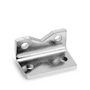
Front/rear flange - D-E-31-100
Front/rear flange - D-E-31-12-16
Front/rear flange - D-E-31-32
Front/rear flange - D-E-31-40
Front/rear flange - D-E-31-50
Front/rear flange - D-E-31-80
Front/rear flange - D-E-32-20
Front/rear flange - D-E-32-25
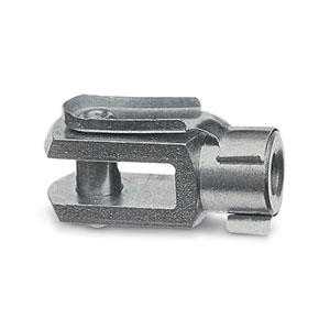
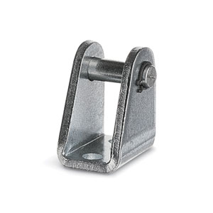
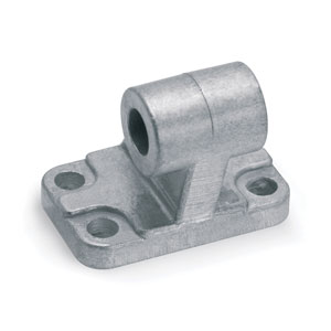
Rod clevis - G-12-16
Rod clevis - G-20
Rod clevis - G-25-32
Rod clevis - G-40
Rod clevis - G-50-63
Rod clevis - G-80-100
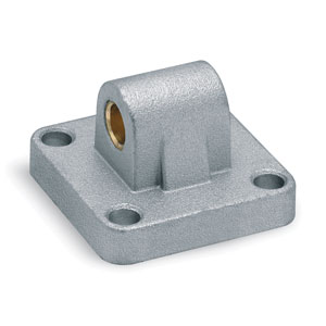
Rear trunnion (female) - C-31-100
Rear trunnion - C-31-32
Rear trunnion - C-31-40
Rear trunnion (female) - C-31-50
Rear trunnion (female) - C-31-63
Rear trunnion - C-31-80
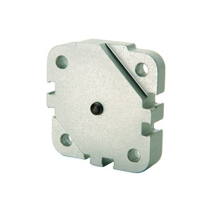
Intermediate bracket - DC-31-12-16
Intermediate bracket - DC-31-20
Intermediate bracket - DC-31-25
Intermediate bracket - DC-31-32
Intermediate bracket - DC-31-40
Intermediate bracket - DC-31-50
Intermediate bracket - DC-31-63
Intermediate bracket - DC-31-80
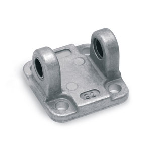
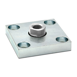
Rear trunnion bracket - I-12-16
Rear trunnion bracket - I-20-25


addtocart.popup.message.success
The requested quantity is partially confirmed
Product {0} is already in your cart with quantity {1}. You can update the quantity from cart page.
Product is not active
The product could not be added to the cart due to insufficient stock
Quantity must be greater than zero
Min allowed quantity for product {0} is {1}
Max allowed quantity for product {0} is {1}
Pack size for product {0} is {1}
It is not possible to add the product with code {0} to this cart
An error occurred, please try again later or contact customer support
Coding example
| 31 | M | 2 | A | 032 | A | 050 |
| 31 |
SERIES 31 = compact magnetic |
|
| M |
VERSION M = male rod thread, mounted with rod nut Mod. U F = female rod thread R = non-rotating with flange only double-acting |
|
| 2 |
OPERATION 1 = single-acting, front spring 2 = double-acting 3 = double-acting, through-rod 4 = single-acting, rear spring 7 = single-acting, through-rod |
PNEUMATIC SYMBOLS CS06 CD08 CD12 CS08 CS10 |
| A |
MATERIALS A = rolled stainless steel AISI 303 rod - AL tube profile |
|
| 032 |
BORE 012 = 12 mm 016 = 16 mm 020 = 20 mm 025 = 25 mm 032 = 32 mm 040 = 40 mm 050 = 50 mm 063 = 63 mm 080 = 80 mm 100 = 100 mm |
|
| A |
DESIGN TYPE A = standard |
|
| 050 | STROKE (see the table) | |
|
= standard V = rod seal FKM W = seals in FKM for high temperatures (140°C), only available in the double-acting, non magnetic version |
| Ø | ØD | ØD1 | D2 | D3 | E1 | F | F1+ | H+ | H1+ | H2 | H3++ | H4 + | K1 | L | L1 | L2 | L3 | T | T1 | SW1 |
| 12 | 6 | 3,5 | M4 | M3 | M5 | 8 | 30 | 38 | 42,5 | 18,5 | 47 | 58,5 | M6 | 29 | 18 | 30 | 16 | 6 | 16 | 5 |
| 16 | 8 | 3,5 | M4 | M4 | M5 | 8 | 30 | 38 | 42,5 | 18,5 | 47 | 62,5 | M8 | 29 | 18 | 30 | 16 | 8 | 20 | 7 |
| 20 | 10 | 4,5 | M5 | M5 | M5 | 8 | 30 | 38 | 42,5 | 18,5 | 47 | 64,5 | M10x1,25 | 36 | 22 | 37,5 | 18 | 10 | 22 | 8 |
| 25 | 10 | 4,5 | M5 | M5 | M5 | 8 | 31,5 | 39,5 | 45 | 18,5 | 50,5 | 67 | M10x1,25 | 40 | 26 | 41,5 | 18 | 10 | 22 | 8 |
| 32 | 12 | 5,5 | M6 | M6 | G1\8 | 8 | 36,5 | 44,5 | 50,5 | 21,5 | 56,5 | 72,5 | M10x1,25 | 50 | 32 | 52 | 20 | 12 | 22 | 10 |
| 40 | 12 | 5,5 | M6 | M6 | G1\8 | 8 | 37,5 | 45,5 | 52 | 21,5 | 58,5 | 74 | M10x1,25 | 60 | 42 | 62,5 | 20 | 12 | 22 | 10 |
| 50 | 16 | 6,5 | M8 | M8 | G1\8 | 8 | 37,5 | 45,5 | 53 | 22,5 | 60,5 | 77 | M12x1,25 | 68 | 50 | 71 | 20 | 12 | 24 | 13 |
| 63 | 16 | 8,5 | M10 | M8 | G1\8 | 8 | 42 | 50 | 57,5 | 24,5 | 65 | 81,5 | M12x1,25 | 87 | 62 | 91 | 25 | 12 | 24 | 13 |
| 80 | 20 | 8,5 | M10 | M10 | G1\8 | 8,5 | 47,5 | 56 | 64 | 24,5 | 72 | 96 | M16x1,5 | 107 | 82 | 111 | 25 | 16 | 32 | 17 |
| 100 | 25 | 8,5 | M10 | M12 | G1\4 | 10,5 | 56 | 66,5 | 76,5 | 31,5 | 86,5 | 116,5 | M20x1,5 | 128 | 103 | 133 | 25 | 20 | 40 | 22 |
1-16/17 results
 Argentina


 Download catalogue
.jpg)
