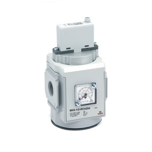
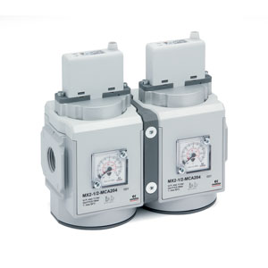
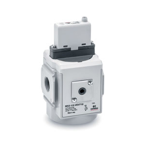
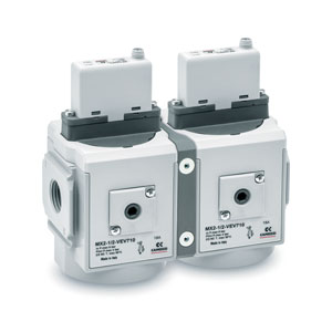
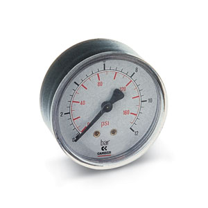
Proportional pressure regulator and proportional flow valve
Series MX-PRO
Regulator and valve ports (Single and Manifold): G1/2
Regulator: with built-in pressure gauge or G1/8 threaded ports
Valve: without pressure gauge
Regulator: with built-in pressure gauge or G1/8 threaded ports
Valve: without pressure gauge
Series MX-PRO electronic proportional pressure regulator is the result of combining advanced technology of Series K8P electronic proportional micro regulator, with reliability and high performance of Series MX2 modular regulators.
This new regulator ensures high precision in pressure regulation, high flow rate and low consumption.
Moreover, it can take the most of Series MX ease of assembly to provide particularly compact Manifolds.
This new regulator ensures high precision in pressure regulation, high flow rate and low consumption.
Moreover, it can take the most of Series MX ease of assembly to provide particularly compact Manifolds.
Series
Accessories
Electric comm.manif.reg. - MX2-1/2-MCA100
Electric comm.manif.reg. - MX2-1/2-MCA102
Electric comm.manif.reg. - MX2-1/2-MCA110
Electric comm.manif.reg. - MX2-1/2-MCA112
Electric comm.manif.reg. - MX2-1/2-MCA200
Electric comm.manif.reg. - MX2-1/2-MCA204
Electric comm.manif.reg. - MX2-1/2-MCA210
Electric comm.manif.reg. - MX2-1/2-MCA214
Electric comm.manif.reg. - MX2-1/2-MCV100
Electric comm.manif.reg. - MX2-1/2-MCV102
Electric comm.manif.reg. - MX2-1/2-MCV110
Electric comm.manif.reg. - MX2-1/2-MCV112
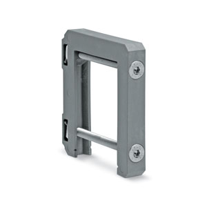
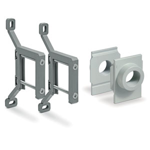
End-plate flanges (pair)s.mx - MX2-1/2-FL
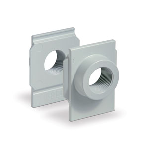
In-out flanges kit - MX2-3/4-FL
In-out flanges kit - MX2-3/8-FL
In-out flanges kit - MX3-3/4-FL
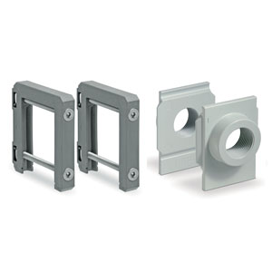
Rap.clamps+flanges kit s. mx - MX2-1/2-JJ
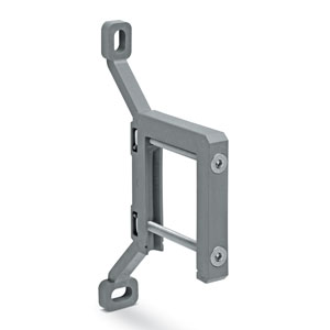
Kit wall brckts + flngs s.mx - MX2-1/2-KK


addtocart.popup.message.success
The requested quantity is partially confirmed
Product {0} is already in your cart with quantity {1}. You can update the quantity from cart page.
Product is not active
The product could not be added to the cart due to insufficient stock
Quantity must be greater than zero
Min allowed quantity for product {0} is {1}
Max allowed quantity for product {0} is {1}
Pack size for product {0} is {1}
It is not possible to add the product with code {0} to this cart
An error occurred, please try again later or contact customer support
| PROPORTIONAL PRESSURE REGULATOR | PROPORTIONAL FLOW VALVE | |
| Construction | modular, compact, diaphragm type | modular, piston type |
| Materials | see material tables on the following pages | see material tables on the following pages |
| Ports | G1/2 | G1/2 |
| Mounting | vertical in-line, wall-mounting (by means of clamps) | vertical in-line, wall-mounting (by means of clamps) |
| Working pressure | 0°C ÷ 50°C | 0°C ÷ 50°C |
| Max inlet pressure | 11 bar (10 bar), 4 bar (3 bar), 1,5 bar (1 bar), 8 bar (7 bar) | 6 bar |
| Regulated pressure | 0,5 ÷ 10 bar, 0,15 ÷ 3 bar, 0,05 ÷ 1 bar, 0,35 ÷ 7 | - |
| Max servo-pilot pressure | 4 bar (3 bar), 11 bar (10 bar), 1,5 bar (1 bar), 8 bar (7 bar) | 4 bar (essential for the proper functioning) |
| Overpressure exhaust | with Relieving (standard) or without Relieving | NO |
| Nominal flow | see flow diagrams on the following pages | see flow diagrams on the following pages |
| Air specifications |
filtered compressed air, non lubricated, class 7.4.4 according to ISO 8573.1 standard. If lubrication is necessary, please use only oils with maximum viscosity of 32 Cst and the version with external servo-pilot supply. The servo-pilot supply air quality class must be 7.4.4 according to ISO 8573.1 standard. Compatible to work with Oxygen |
filtered compressed air, non lubricated, class 7.4.4 according to ISO 8573.1 standard. If lubrication is necessary, please use only oils with maximum viscosity of 32 Cst and the version with external servo-pilot supply. The servo-pilot supply air quality class must be 7.4.4 according to ISO 8573.1 standard. Compatible to work with Oxygen |
| Pressure gauge | with built-in pressure gauge (standard) with G1/8 port | without pressure gauge |
| Analogical input | 0-10 V DC Ripple ≤ 0,2%; 4 – 20 mA |
0-10 V DC Ripple ≤ 0,2%; 4 – 20 mA |
| Analogical output | 0,5 - 9,5 V DC [ Feedback ] | not relevant |
| Electrical supply | 24 V DC ±10% | 24 V DC ± 10% |
| Electrical connection | M8 4 Pin (Male) | M8 4 Pin (Male) |
| Linearity | ≤ ± 1% FS | ± 5% FS |
| Hysteresis | ± 0,5% FS | ± 8% FS |
| Repeatability | ± 0,5% FS | ± 0,5% FS |
| Sensibility | 0,3% FS | 0,5% FS |
| Protection class | IP51 | IP51 |


addtocart.popup.message.success
The requested quantity is partially confirmed
Product {0} is already in your cart with quantity {1}. You can update the quantity from cart page.
Product is not active
The product could not be added to the cart due to insufficient stock
Quantity must be greater than zero
Min allowed quantity for product {0} is {1}
Max allowed quantity for product {0} is {1}
Pack size for product {0} is {1}
It is not possible to add the product with code {0} to this cart
An error occurred, please try again later or contact customer support
CODING EXAMPLE
| MX | 2 | - | 1/2 | - | R | CV | 2 | 0 | 4 | - | LH | - | OX1 |
| MX | SERIES | |
| 2 |
SIZE: 2 = G1/2 |
|
| 1/2 |
PORTS: 1/2 = G1/2 |
|
| R |
FUNCTIONING: R = pressure regulator M = Manifold pressure regulator |
V = flow valve W = Manifold flow valve |
| CV |
COMMAND: CV = electrical command 0-10 V DC (regulator only) CA = electrical command 4-20 mA (regulator only) |
XV = electrical command 0-10 V DC with external servo pilot supply XA = electrical command 4-20 mA DC with external servo pilot supply EV = electrical command 0-10 V DC with external servo pilot supply EA = electrical command 4-20 mA with external servo pilot supply |
| 2 |
REGULATOR SETTING RANGE: 1 = working pressure 0,15 ÷ 3 bar 2 = working pressure 0,5 ÷ 10 bar * 3 = working pressure 0,05 ÷ 1 bar 4 = working pressure 0,35 ÷ 7 bar |
VALVE SETTING RANGE: 7 = flow valve |
| 0 |
DESIGN TYPE: 0 = relieving (regulator only) 1 = without relieving |
|
| 4 |
PRESSURE GAUGE: 0 = without pressure gauge, with threaded port for gauges (for OX1 version) 2 = with built-in pressure gauge 0-6 bar (regulator only) |
3 = with built-in pressure gauge 0-10 bar (regulator only) 4 = with built-in pressure gauge 0-12 bar (regulator only) |
| LH |
FLOW DIRECTION: = from left to right (standard) LH = from right to left |
|
| OX1 | = suitable for use with oxygen |
* For the configurations with the pressure regulation range of 10 bar in the OX1 version, the version with external servo pilot air supply is mandatory.
Further details about the assembly of a single component with fixing flanges or wall-mounting can be found in the AIR TREATMENT catalogue, section SERIES MX ASSEMBLED FRL.
1-9/9 results
 Gibraltar


 Download catalogue