Compact cylinders Tandem and Multi-position versions
Series 32
Double-acting, magnetic
ø 25, 40, 63, 100 mm
ø 25, 40, 63, 100 mm
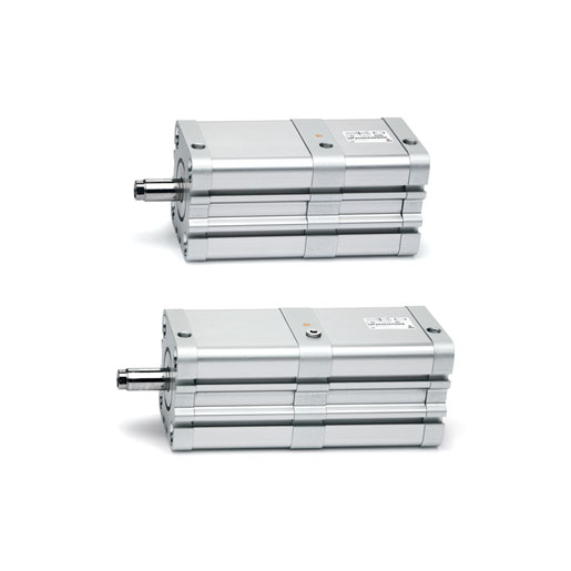
Thanks to their great compactness Series 32 cylinders, Tandem and Multi-position, are suitable to be installed within confined spaces and can be used with the same mounting elements of other standard cylinders ISO15552.
The Tandem version enables to obtain up to 2 times the thrust force of a normal cylinder (standard traction force), while the Multi-position version can obtain up to three positions with one cylinder only.
The Tandem version enables to obtain up to 2 times the thrust force of a normal cylinder (standard traction force), while the Multi-position version can obtain up to three positions with one cylinder only.
Series
Accessories
Cylinders +pos.sr.32 - 32F2A025A5/10N
Cylinders tandem sr.32 - 32F2A025A005N2
Cylinders +pos.sr.32 - 32F2A025A10/15N
Cylinders +pos.sr.32 - 32F2A025A10/20N
Cylinders +pos.sr.32 - 32F2A025A10/40N
Cylinders +pos.sr.32 - 32F2A025A10/60N
Cylinders tandem sr.32 - 32F2A025A010N2
Cylinders +pos.sr.32 - 32F2A025A15/20N
Cylinders +pos.sr.32 - 32F2A025A15/30N
Cylinders +pos.sr.32 - 32F2A025A15/45N
Cylinders tandem sr.32 - 32F2A025A015N2
Cylinders +pos.sr.32 - 32F2A025A20/30N
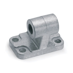
Foot mount - B-31-12-16
Foot mount - B-31-25
Foot mount - B-32-20
Foot mount - B-41-100
Foot mount - B-41-125
Foot mount - B-41-32
Foot mount - B-41-40
Foot mount - B-41-50
Foot mount - B-41-63
Foot mount - B-41-80
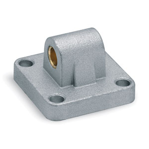
Front/rear trunnion (female) - C-H-41-100
Front/rear trunnion (female) - C-H-41-125
Rear trunnion (female) - C-H-41-63
Front/rear trunnion (female) - C-H-41-80
Front/rear flange - D-E-31-12-16
Front/rear flange - D-E-32-20
Front/rear flange - D-E-32-25
Front/rear flange - D-E-41-100
Front/rear flange - D-E-41-125
Front/rear flange - D-E-41-32
Front/rear flange - D-E-41-40
Front/rear flange - D-E-41-50
Front/rear flange - D-E-41-63
Front/rear flange - D-E-41-80
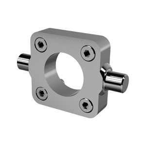
Rear trunnion (male) - L-31-12-16
Rear trunnion (male) - L-32-20
Rear trunnion (male) - L-32-25
Rear trunnion (male) - L-41-100
Rear trunnion (male) - L-41-125
Rear trunnion (male) - L-41-32
Rear trunnion (male) - L-41-40
Rear trunnion (male) - L-41-50
Rear trunnion (male) - L-41-63
Rear trunnion (male) - L-41-80
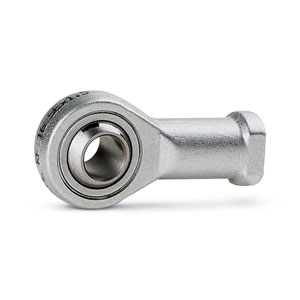
Rear trunnion (ball joint) - R-41-100
Rear trunnion - R-41-125
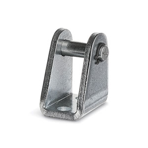
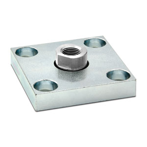
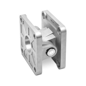
Rear trunnion bracket - I-20-25
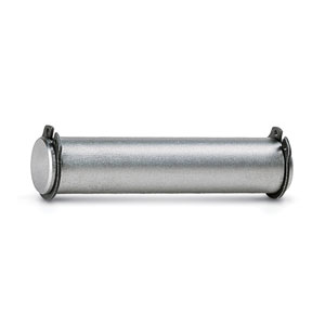
Clevis pin - S-50
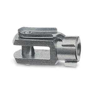
Rod clevis - G-12-16
Rod clevis - G-20
Rod clevis - G-25-32
Rod clevis - G-40
Rod clevis - G-50-63
Rod clevis - G-80-100
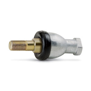
Swivel ball joint - GA-50-63
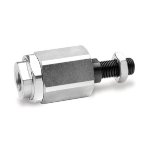
Compensator joint m10x1,25 - GKF-25-32
Coupler m12x1,25 - GKF-40
Compensator joint m16x1,50 - GKF-50-63
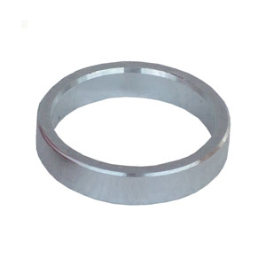
Centering ring for end caps - TR-32-100
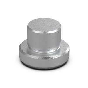
Centering pin for end caps - TS-32-20


addtocart.popup.message.success
The requested quantity is partially confirmed
Product {0} is already in your cart with quantity {1}. You can update the quantity from cart page.
Product is not active
The product could not be added to the cart due to insufficient stock
Quantity must be greater than zero
Min allowed quantity for product {0} is {1}
Max allowed quantity for product {0} is {1}
Pack size for product {0} is {1}
It is not possible to add the product with code {0} to this cart
An error occurred, please try again later or contact customer support
| Construction | Compact profile |
| Operation | Double-acting, magnetic |
| Material | Body and end-blocks = anodized AL rod = rolled stainless steel AISI 303 piston = anodized AL rod seal, OR end-block and piston seal = PU |
| Mounting | With threaded holes on the end blocks flange – feet – trunnion |
| Strokes min. and max. (1) Multi-position | Series 32F, 32M Ø25 = 5-300 mm (dimension x2) Series 32F, 32M Ø40 - 63 = 5-400 mm (dimension x2) Series 32F, 32M Ø100 = 5-500 mm (dimension x2) |
| Strokes min. and max. (1) Tandem | Series 32F, 32M Ø25 = 5-80 mm Series 32F, 32M Ø40 - 63 - 100 = 5-100 mm |
| Operating temperature | 0°C ÷ 80°C (with dry air -20°C) |
| Operating pressure | 1 ÷ 10 bar |
| Fluid | Clean air, without lubrication. If lubricated air is used, it is recommended to use oil ISOVG32. Once applied the lubrication should never be interrupted. |
| Operating speed | 10 ÷ 1000 mm\sec (without load) |
(1) the minimum stroke for the use of the sensors is 10 mm.


addtocart.popup.message.success
The requested quantity is partially confirmed
Product {0} is already in your cart with quantity {1}. You can update the quantity from cart page.
Product is not active
The product could not be added to the cart due to insufficient stock
Quantity must be greater than zero
Min allowed quantity for product {0} is {1}
Max allowed quantity for product {0} is {1}
Pack size for product {0} is {1}
It is not possible to add the product with code {0} to this cart
An error occurred, please try again later or contact customer support
Coding example
| 32 | M | 2 | A | 040 | A | 050 | N | 2 |
| 32 |
SERIES compact magnetic |
|
| M |
VERSION M = male rod thread, mounted with rod nut Mod. U F = female rod thread |
|
| 2 |
OPERATION 2 = double-acting |
PNEUMATIC SYMBOLS CDPP |
| A |
MATERIALS A = anodized aluminium profile, end blocks and piston PU seals (rod - OR end block and piston) |
|
| 040 |
BORE 025 = 25 mm 040 = 40 mm 063 = 63 mm 100 = 100 mm |
CD5T, CD6T, CD7T CD5T, CD6T, CD7T CD2T, CD3T, CD4T CD5T, CD6T, CD7T |
| A |
CONSTRUCTION A = standard |
|
| 050 |
STROKE - Tandem stroke in mm - Multi-position X1mm/X2mm. Insert the strokes without the initial 0 (see application scheme) |
|
| N | Tandem and Multi-position | |
| 2 |
STAGES (for Tandem version only) 2 = 2 stages |
1-16/27 results
 Latvia



 Download catalogue
.jpg)
.jpg)
.jpg)
.jpg)
.jpg)
