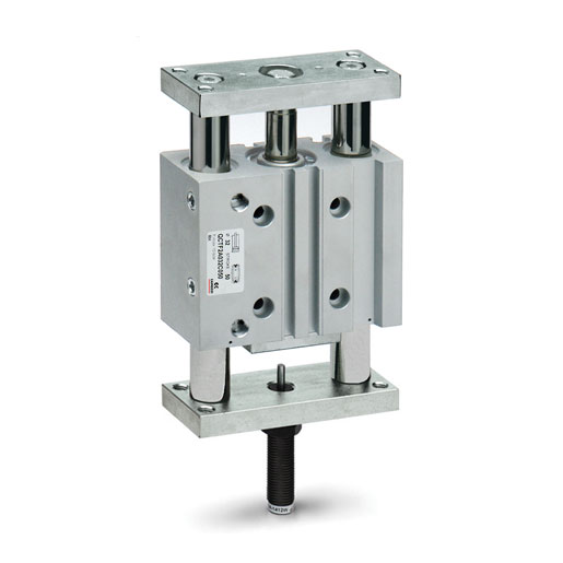
QCTF2A025C050
Guided slide units 1 sa
| Operation | Double-acting |
| Name of Series | QC |
| Stroke | 50 |
| Materials | Anodized aluminium body - rolled stainless steel piston rod AISI 303 rolled stainless steel AISI 420B colums for QCTF - hardened steel C50 colums for QCBF |
| Version | Double flange |
| Cushioning | One shock absorber located on the rear flange |
| Type of bearing | Sintered bronze bushes |
| Bore | 25 |
Accessories
there are no salable codes online
Look in the "Accessory" tab for the Configurator


addtocart.popup.message.success
The requested quantity is partially confirmed
Product {0} is already in your cart with quantity {1}. You can update the quantity from cart page.
Product is not active
The product could not be added to the cart due to insufficient stock
Quantity must be greater than zero
Min allowed quantity for product {0} is {1}
Max allowed quantity for product {0} is {1}
Pack size for product {0} is {1}
It is not possible to add the product with code {0} to this cart
An error occurred, please try again later or contact customer support
Cylinders QCTF and QCBF type "C"
+ = add the stroke once
++ = add the stroke twice
Note: for out of standard intermediate strokes (ex. stroke 35), consider the immediately higher stroke dimensions (ex. stroke 40).
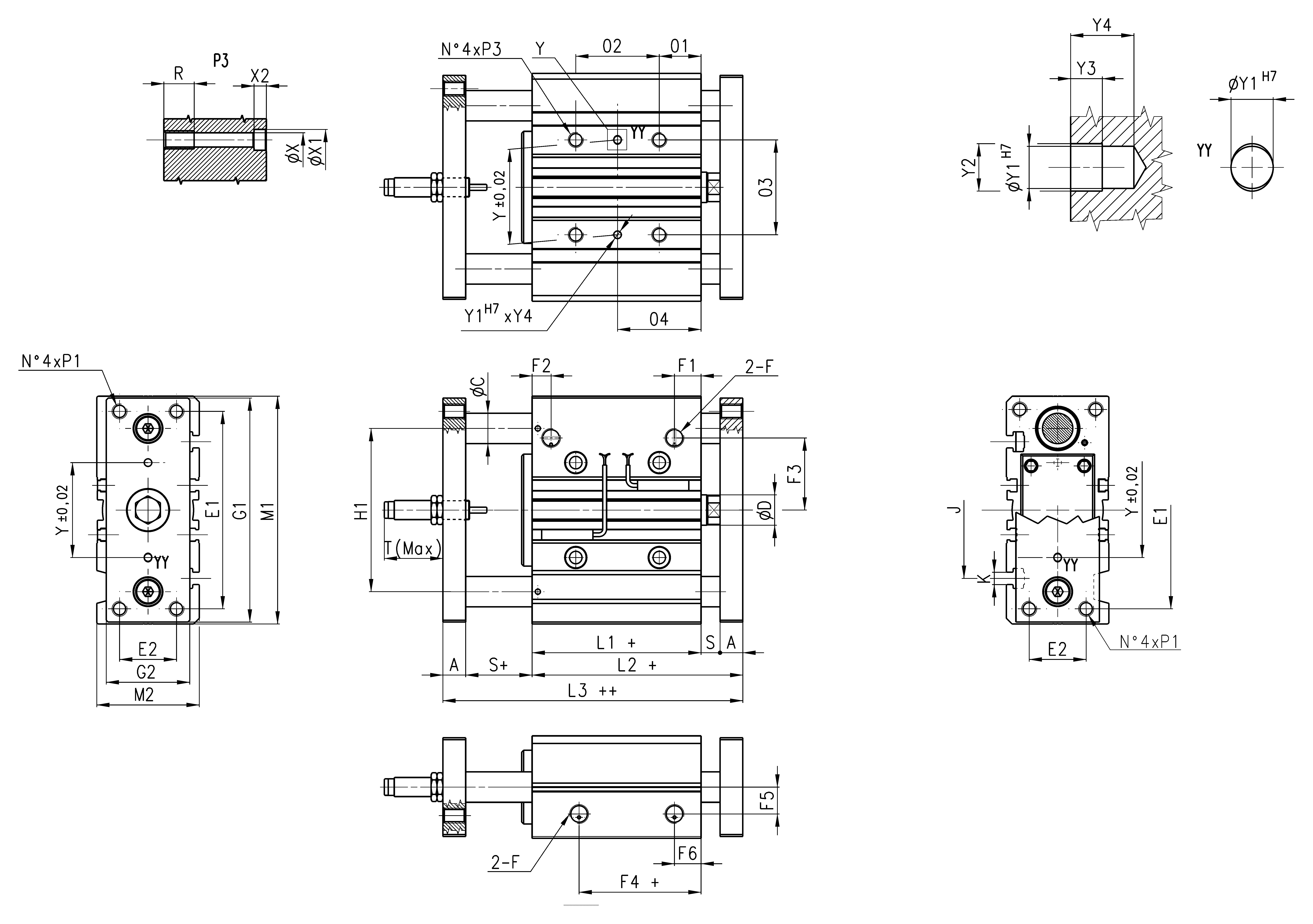
In case of use of lateral ports, unscrew the related threaded caps, screw them in the front ports and tighten them up to the cylinder surface (not tighter) having care to use a proper sealer.
| Ø | P1 | P3 | T | Y | Y1 | Y2 | Y3 | Y4 | X | X1 | X2 | J | K | Shock absorber | Δ stroke (mm) | adjustment range cyl. stroke mm |
| 20 | M5x0,8 | M6x1 | 37 | 28 | 3 | 3,5 | 3 | 6 | 5,5 | 9 | 5 | 44 | M5 | SA-1007 W | 0 ÷ 25 | -15 ÷ -25 |
| 25 | M6x1 | M6x1 | 37 | 34 | 4 | 4,5 | 3 | 6 | 5,5 | 9 | 5 | 50 | M5 | SA-1007 W | 0 ÷ 25 | -15 ÷ -25 |
| 32 | M8x1,25 | M8x1,25 | 55 | 42 | 4 | 4,5 | 3 | 6 | 6,5 | 11 | 6,5 | 63 | M6 | SA-1412 W | 0 ÷ 35 | -18 ÷ -35 |
| 40 | M8x1,25 | M8x1,25 | 55 | 50 | 4 | 4,5 | 3 | 6 | 6,5 | 11 | 6,5 | 72 | M6 | SA-1412 W | 0 ÷ 35 | -18 ÷ -35 |
|
02 stroke 20-30 |
02 stroke 40-100 |
02 stroke 125-200 |
04 stroke 20-30 |
04 stroke 40-100 |
04 stroke 125-200 |
QCBF ØC |
QCTF ØC |
|||||||||
| 20 | 24 | 44 | 120 | 29 | 39 | 77 | 10 | 12 | ||||||||
| 25 | 24 | 44 | 120 | 29 | 39 | 77 | 12 | 16 | ||||||||
| 32 | 24 | 48 | 124 | 33 | 45 | 83 | 16 | 20 | ||||||||
| 40 | 24 | 48 | 124 | 34 | 46 | 84 | 16 | 20 |
| Ø | A | D | E1 | E2 | F | F1 | F2 | F3 | F4 | F5 | F6 | G1 | G2 | H1 | L1 | L2 | L3 | M1 | M2 | 01 | 03 | R | S |
| 20 | 10 | 10 | 70 | 18 | 1/8 | 10,5 | 10,5 | 25 | 12,5 | 11,5 | 10,5 | 81 | 30 | 54 | 37 | 53 | 69 | 83 | 36 | 17 | 28 | 12 | 6 |
| 25 | 10 | 12 | 78 | 26 | 1/8 | 11,5 | 8 | 28,5 | 12,5 | 13,5 | 11,5 | 91 | 40 | 64 | 37,5 | 53,5 | 69,5 | 93 | 42 | 17 | 34 | 12 | 6 |
| 32 | 12 | 16 | 96 | 30 | 1/8 | 12,5 | 9,5 | 34 | 7 | 15 | 12,5 | 110 | 45 | 78 | 37,5 | 59,5 | 81,5 | 112 | 48 | 21 | 42 | 16 | 10 |
| 40 | 12 | 16 | 104 | 30 | 1/8 | 13 | 12 | 38 | 13 | 18 | 13 | 118 | 45 | 86 | 44 | 66 | 88 | 120 | 54 | 22 | 50 | 16 | 10 |
1-4/4 results
 Poland



 Download catalogue

