Series
Accessories
there are no salable codes online
If you have entered Filters, try changing them or look in the "Configurator" tab
there are no salable codes online
Look in the "Accessory" tab for the Configurator


addtocart.popup.message.success
The requested quantity is partially confirmed
Product {0} is already in your cart with quantity {1}. You can update the quantity from cart page.
Product is not active
The product could not be added to the cart due to insufficient stock
Quantity must be greater than zero
Min allowed quantity for product {0} is {1}
Max allowed quantity for product {0} is {1}
Pack size for product {0} is {1}
It is not possible to add the product with code {0} to this cart
An error occurred, please try again later or contact customer support
MULTIPOLE VERSION CODING EXAMPLE
In presence of identical consequent codes both for the subbases as for the valves you need to substitute the letter with the number.
Ex: HN5M-03A-ABCS-MMCCBBB-A is converted to HN5M-03A-ABCS-2M2C3B-A.
Ex: HN5M-03A-ABCS-MMCCBBB-A is converted to HN5M-03A-ABCS-2M2C3B-A.
| HN | 5 | M | 03A | 2B8M4C | A |
| HN | SERIES | ||
| 5 |
SIZE: 1 = 10.5 2 = 21 5 = Mixed |
||
| M |
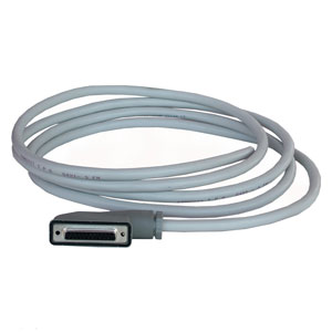
ELECTRICAL CONNECTION: M = Multipole 25 pin PNP N = Multipole 25 pin NPN H = Multipole 37 pin PNP L = Multipole 37 pin NPN |
||
| 03A |
CONNECTION: 000 = without connector/cable |
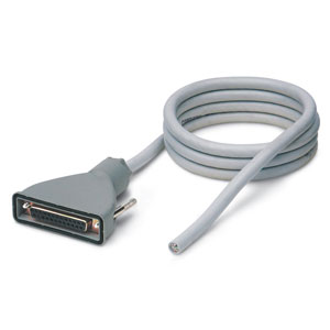
CONNECTOR WITH CABLE AXIAL OUTPUT: 03A = 3m 05A = 5m 10A = 10m 15A = 15m 20A = 20m 25A = 25m CONNECTOR WITH CABLE RADIAL OUTPUT: 03R = 3m 05R = 5m 10R = 10m 15R = 15m 20R = 20m 25R = 25m |
CONNECTOR WITHOUT CABLE: 4XA = 25 pins axial 4XR = 25 pins radial 9XA = 37 pins axial 9XR = 37 pins radial |
| 2B8M4C |
SOLENOID VALVES Size 1 and 2: 0 = island without solenoid valves M = 5/2 Monostable B = 5/2 Bistable V = 5/3 Centres Closed C = 2 x 3/2 NC A = 2 x 3/2 NO G = 1 x 3/2 NC + 1 x 3/2 NO E = 2 x 2/2 NC F = 2 x 2/2 NO I = 1 x 2/2 NC + 1 x 2/2 NO L = free position |
SOLENOID VALVE + PRESSURE REGULATOR on channel 1 (size 2 only): N = 5/2 Monostable P = 5/2 Bistable Q = 5/3 Centres Closed R = 2 x 3/2 NC S = 2 x 3/2 NO T = 1 x 3/2 NC + 1 x 3/2 NO U = 2 x 2/2 NC X = 2 x 2/2 NO Y = 1 x 2/2 NC + 1 x 2/2 NO |
|
| A |
THREADED TERMINAL PLATES: A = 1, 12/14 in common 3/5, 82/84 threaded ports B = 1, 12/14 separated 3/5, 82/84 threaded ports C = 1, 12/14 in common 3/5, 82/84 with integrated silencer D = 1, 12/14 separated 3/5, 82/84 with integrated silencer |
TERMINAL PLATES with FITTINGS FOR TUBE Ø 8 on PORT 1: E = 1, 12/14 in common 3/5, 82/84 conveyable F = 1, 12/14 separated 3/5, 82/84 conveyable G = 1, 12/14 in common 3/5, 82/84 with integrated silencer H = 1, 12/14 separated 3/5, 82/84 with integrated silencer |
TERMINAL PLATES with FITTINGS FOR TUBE Ø 10 on PORT 1: I = 1, 12/14 in common 3/5, 82/84 conveyable L = 1, 12/14 separated 3/5, 82/84 conveyable M = 1, 12/14 in common 3/5, 82/84 with integrated silencer N = 1, 12/14 separated 3/5, 82/84 with integrated silencer |
FIELDBUS VERSION CODING EXAMPLE
X, Y and K sub-bases will be equipped with threads or cartridges of the same size of port 1, see the choice "Type of terminal plates". In presence of identical consequent codes both for sub-bases and for valves, you need to substitute the letter with the number.
Ex: HN501-ABCD-ABCS-MMCCBBB-A is converted to HN501- ABCD-ABCS-2M2C3B-A.
Ex: HN501-ABCD-ABCS-MMCCBBB-A is converted to HN501- ABCD-ABCS-2M2C3B-A.
CODING EXAMPLE OF MULTIPOLE AND FIELDBUS INTERFACES - Accessories
Detailed descriptions of the available accessories can be found in the components list on page 1.40.08 (Multipole version) e 1.40.09 (Fieldbus version)
CODING EXAMPLE OF SINGLE VALVE (Spare part)
Detailed descriptions of the available accessories can be found in the components list on page 1.40.08 (Multipole version) e 1.40.09 (Fieldbus version)
CODING EXAMPLE OF SUBBASES - Accessories
Detailed descriptions of the available accessories can be found in the components list on page 1.40.08 (Multipole version) e 1.40.09 (Fieldbus version)
NOTE: subbases are always supplied without connection fittings.
NOTE: subbases are always supplied without connection fittings.
| A |
| A |
SUBBASE: A = through - M7 threads AZ = through - M7 threads, monostable D = channel 1, 3, 5 closed - M7 threads DZ = channel 1, 3, 5 closed - M7 threads, monostable G = channel 3, 5 closed - M7 threads GZ = channel 3, 5 closed - M7 threads, monostable P = through - G1/4 threads Q = through - G1/8 threads X = supplementary supply and exhaust Y = supplementary supply and exhaust with integrated silencer W = supply from the exhausts K = separation of electrical supply and supplementary pneumatic supply |
SEAL: T = diaphragm seal for the closure of channels 1, 3, 5 U = diaphragm seal for the closure of channel 1 V = diaphragm seal for the closure of channels 3, 5 P = through |
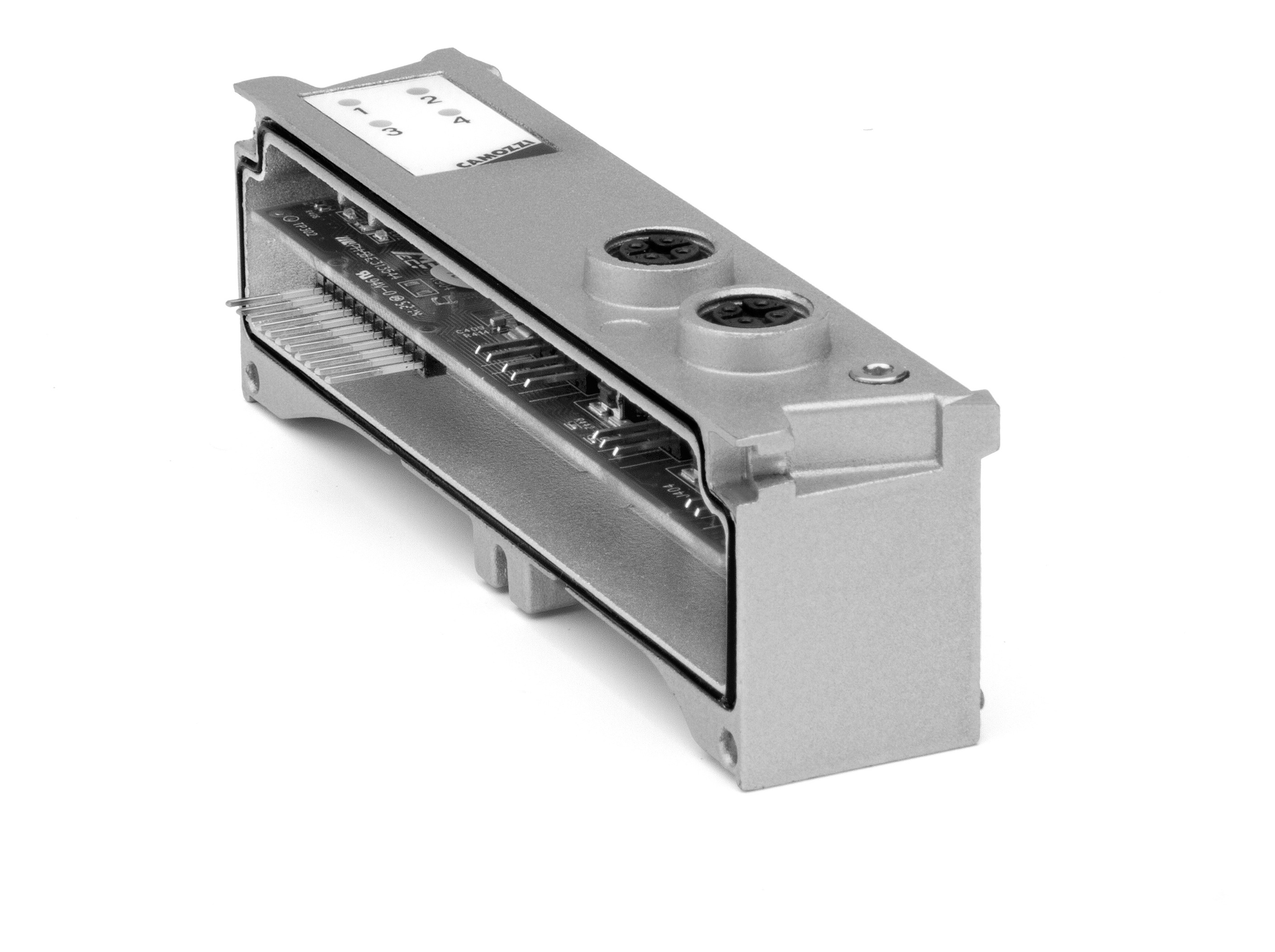
Digital power output module Mod. ME3-0004-DL
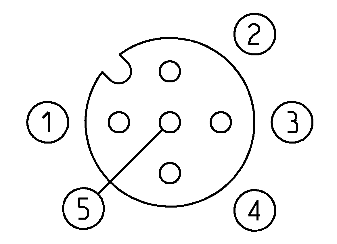
The digital output module can be connected only in presence of a CPU or Expansion module and can be mixed with other either digital or analog Input and Output devices and with the initial module of the subnet. It has two M12 A 5 pin female connections, each connection can manage 2 digital outputs and can provide a maximum of 10 W to 24 V DC. The device is useful to pilot a bistable valve or two monostable valves for each connector, or to activate the electric coils or other electric devices with maximum absorption of 10 W to 24 V DC. Connecting two outputs to one electric device only and activating them simultaneously, it is possible to provide maximum 20 W to 24 V DC.
| Mod. | Coding reference | Number of digital outputs | Connection | Number of connectors | Dimensions | Signalling | Sensor supply | Max power for M12 connector | Max power for digital output | Type of signal | Protection class | Operating temperature | Weight |
| ME3-0004-DL | Q | 4 | M12 A 5 pin female | 2 | 122 x 25 mm | 1 yellow led for each output | 24 V DC | 20 W | 10 W | NPN | IP65 | 0 ÷ 50°C | 100 g |
1-16/22 results
 Turkey


 Download catalogue
