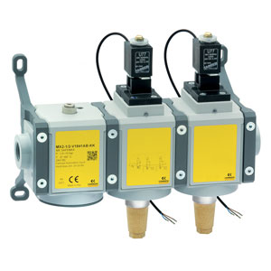
3/2-way quick exhaust safety valves with soft start
Série MX SAFEMAX
Connexion: G1/2
In this configuration, in addition to the characteristics of the versions with solenoid valves only, the soft start function has been integrated, which allows a gradual introduction of pressure into the system. Its positioning upstream of the solenoid valves allows, even in the event of an anomaly, to always have the maximum discharge flow rate. Thanks to the internal construction solutions it was possible to maintain the design and dimensions of the standard product, no further interface plates are necessary. Please note: the safety valve alone is not sufficient to guarantee the safety function. Its activation requires the use of a supervisor device.
The Machinery Directive (MD) 2006/42 / EC establishes the safety requirements that a machine must respect in order to protect the health of people during its use. Series MX SAFEMAX solenoid valves comply with ISO 13849-1, regarding the safe design of control systems that perform safety functions
The Machinery Directive (MD) 2006/42 / EC establishes the safety requirements that a machine must respect in order to protect the health of people during its use. Series MX SAFEMAX solenoid valves comply with ISO 13849-1, regarding the safe design of control systems that perform safety functions
Séries
Accessoires
Il n'existe pas de codes vendables en ligne
Si vous avez saisi des filtres, essayez de les modifier ou consultez l'onglet "Configurateur".
Il n'existe pas de codes vendables en ligne
Regardez dans l'onglet "Accessoire" pour le Configurateur


addtocart.popup.message.success
La quantité demandée est partiellement confirmée
Le produit {0} est déjà dans votre panier avec la quantité {1}. Vous pouvez mettre à jour la quantité à partir de la page du panier.
Le produit n'est pas actif
Le produit n'a pas pu être ajouté à votre panier en raison d'un stock insuffisant.
La quantité doit être supérieure à zéro
La quantité minimale autorisée pour le produit {0} est {1}
La quantité maximale autorisée pour le produit {0} est {1}
Le conditionnement le produit {0} est {1}
Il n''est pas possible d''ajouter le produit avec le code {0} à votre panier.
Une erreur s'est produite, veuillez réessayer plus tard ou contacter le service client.
| Construction | Modulaire, compact, technologie à tiroir |
| Matériaux | Voir tableau des Materiaux |
| Raccordements | G1/2 |
| Montage | En ligne (vertical) murale (au moyen d'étriers) |
| Température de fonctionnement | -5°C à +50°C jusqu'à 16 bars(avec point de rosée du fluide inférieure de 2° par rapport à la température mini de fonctionnement ) -5°C à +60°C jusqu'à 10 bars(avec point de rosée du fluide inférieure de 2° par rapport à la température mini de fonctionnement ) |
| Pression de fonctionnement | Vanne manuelle : -0,8 ÷ 10 bars Vanne électro-pneumatique : 2 ÷ 10 bars Vanne pneumatique ou asservie : -0,8 ÷ 10 bars (avec pilotage 3.5 à 10 bars) |
| Débit nominal (6 bar) | Voir DIAGRAMMES DE DÉBIT sur les pages suivantes |
| Fluide | MX2 = 6000 Nl/min MX3 = 9200 Nl/min |
| SPÉCIFICATIONS DE LA BOBINE | |
| Raccordement | Avec fils, M8 |
| Tension | 24V DC (±10%) 3,1W (ED 100%) |
| SPÉCIFICATIONS DU CAPTEUR | |
| Fonctionnement | Magnétorésistif |
| Type de contact | N.O. PNP |
| Courant maximum | Version EX : 200 mA 0,65 W Version UL : 100 mA 3 W Version CE : 200 mA 5,5W |
| CONFORMITÉ À LA NORME EN ISO 13849-1 | |
| Niveau de performance accessible (PL) | Version simple: catégorie 2, PLd Version double: catégorie 4, PLe |
| B10d | 2.000.000 cycles |
Exemple de codification - Valve unique
| MX | 2 | 3/8 | V | 01 | LH | 0 | A | B | KK | LH |
| MX | SÉRIE | |
| 2 | TAILLE | |
| 3/8 |
RACCORDEMENT 1/2 = G1/2" |
|
| V | VANNE 3/2 | |
| 01 |
COMMANDE 01 = commande manuelle= 16 = commande électro-pneumatique 17 = commande électro-pneumatique asservie 36 = commande pneumatique |
|
| LH |
SENS DU FLUX = de gauche à droite (standard) LH = de droite à gauche |
|
| 0 |
ACCESSORIES 0 = without silencer 1 = with silencer |
|
| A |
SENSOR A = UL sensor, 2 mt cable B = UL sensor, 5 mt cable C = ATEX sensor, 2 mt cable |
D = ATEX sensor, 5 mt cable E = CE sensor M8 connector, 300 mm cable |
| B |
VERSION A = Atex B = UL C = CE |
sensor and version must comply with the same Standard / directive AB, BB - CA, DA - EC |
| KK |
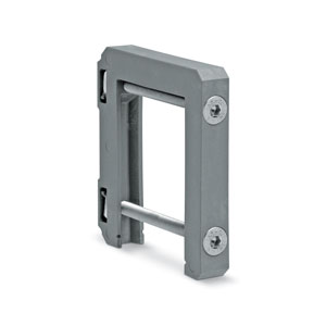
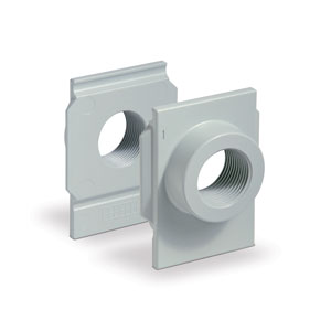
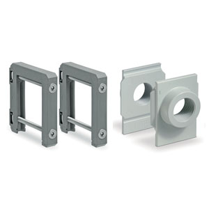
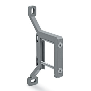
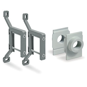
MOUNTING = without mounting accessories Z = central wall clamps Y= central wall brackets |
HH = side quick clamps and flanges JJ= side wall clamps and flanges KK = side wall brackets and flanges |
| LH |
FLOW DIRECTION = from left to right (standard) LH = from right to left |
Exemple de codification - Double valve
| MX | 2 | - | 1/2 | - | V | 18 | 4 | 0 | A | B | - | KK | - | LH |
| MX | SÉRIE | |
| 2 | TAILLE | |
| 1/2 |
PORT 1/2 =G1/2 |
|
| V |
COMPONENT V = 3/2 way valve |
|
| 18 |
CONSTRUCTION 18 = internal servo-pilot with soft start valve 19 = external servo-pilot with soft start valve |
|
| 4 |
CHANNEL 4 = double |
|
| 0 |
ACCESSORIES 0 = without silencer 1 = with silencer |
|
| A |
SENSOR A = UL sensor, 2 mt cable B = UL sensor, 5 mt cable C = ATEX sensor, 2 mt cable |
D = sensore ATEX cavo 5mt E = sensore CE connettore M8 cavo 300mm |
| B |
VERSION A = Atex B = UL C = CE |
sensor and version must comply with the same Standard / directive AB, BB - CA, DA - EC |
| KK |
MOUNTING = without mounting accessories Z = central wall clamps Y= central wall brackets |
HH = side quick clamps and flanges JJ= side wall clamps and flanges KK = side wall brackets and flanges |
| LH |
FLOW DIRECTION = from left to right (standard) LH = from right to left |
 Belgique


 Télécharger le catalogue
