Short-stroke cylinders
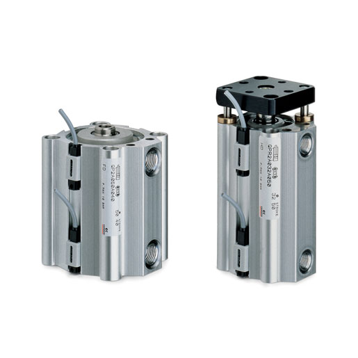
Series QP - QPR
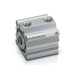
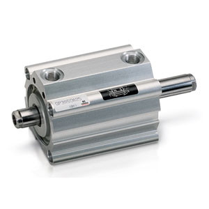
Series QP: single and double-acting, magnetic
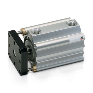
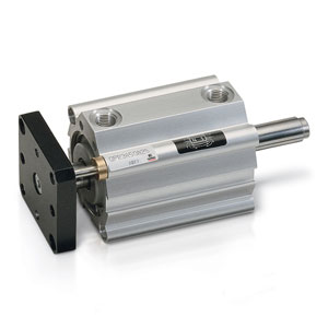
Series QPR: double-acting magnetic, non-rotating
ø 12, 16, 20, 25, 32, 40, 50, 63, 80, 100 mm
Series QPR: double-acting magnetic, non-rotating
ø 12, 16, 20, 25, 32, 40, 50, 63, 80, 100 mm
Series QP - QPR cylinders are available in 10 bore sizes, from ø12 to ø100. Their compact dimension allows the installation in small spaces. Because of their particular construction, they can be mounted by means of feet or trunnion.
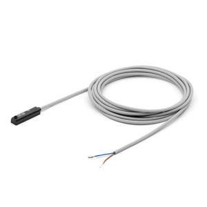
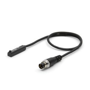
The guides are manufactured in the external profile parallel to the sliding axis on three sides. These are used to locate the switches that sense the piston position. The non rotating guides make the QPR suitable for supply operations and for handling equipment.
The guides are manufactured in the external profile parallel to the sliding axis on three sides. These are used to locate the switches that sense the piston position. The non rotating guides make the QPR suitable for supply operations and for handling equipment.
Series
Accessories
Short-stroke cyl. ser. qp - QP2A016A025
Short-stroke cyl. ser. qp - QP2A016A030
Short-stroke cylinders - QP2A016A035
Short-stroke cyl. ser. qp - QP2A020A005
Short-stroke cyl. ser. qp - QP2A020A010
Short-stroke cyl. ser. qp - QP2A020A015
Short-stroke cyl. ser. qp - QP2A020A020
Short-stroke cyl. ser. qp - QP2A020A025
Short-stroke cyl. ser. qp - QP2A020A030
Short-stroke cyl. ser. qp - QP2A020A035
Short-stroke cyl. ser. qp - QP2A020A040
Short-stroke cyl. ser. qp - QP2A020A050
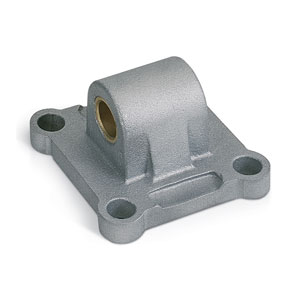
Trunnion (male) - L-QP-100
Trunnion (male) - L-QP-40
Trunnion (male) - L-QP-50
Trunnion (male) - L-QP-80
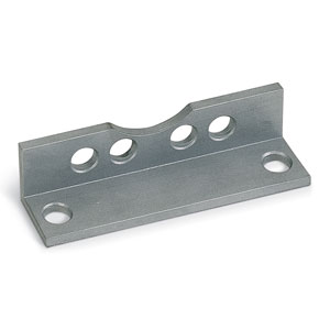
Cylinder brackets - B-QP-100
Cylinder brackets - B-QP-32
Foot mount - B-QP-40
Cylinder brackets - B-QP-50
Cylinder brackets - B-QP-63
Cylinder brackets - B-QP-80


addtocart.popup.message.success
The requested quantity is partially confirmed
Product {0} is already in your cart with quantity {1}. You can update the quantity from cart page.
Product is not active
The product could not be added to the cart due to insufficient stock
Quantity must be greater than zero
Min allowed quantity for product {0} is {1}
Max allowed quantity for product {0} is {1}
Pack size for product {0} is {1}
It is not possible to add the product with code {0} to this cart
An error occurred, please try again later or contact customer support
| Type of construction | Series QP: compact profile Series QPR: compact with non rotating guides |
| Operation | Series QP: single and double-acting Series QPR: double-acting |
| Materials | body: anodized AL rod: rolled stainless steel piston seals: PU rod seals: PU (Ø 12 ÷ 25 mm) - NBR (Ø 32 ÷ 100 mm) |
| Operating temperature | 0°C ÷ 80°C (with dry air -20°C) |
| Assembly | by means of screws or brackets |
| Operating pressure | 1 ÷ 10 bar (double-acting); 2 ÷ 10 bar (single-acting) |
| Fluid | filtered air, without lubrication. If lubricated air is used, it is recommended to use oil ISOVG32. Once applied the lubrication should never be interrupted. |
| Strokes (min-max) | Series QP: 1 ÷ 150 mm (ø12 ÷ ø 25) - 1 ÷ 200 mm (ø 32 ÷ ø 100) Series QPR: 1 ÷ 50 mm (ø 12) - 1 ÷ 75 mm (ø 16) - 1 ÷ 100 mm (ø 20 ÷ ø 100) |
| Strokes | the minimum stroke for use of the sensors is 10 mm |
| Bores | ø 12, 16, 20, 25, 32, 40, 50, 63, 80, 100 |


addtocart.popup.message.success
The requested quantity is partially confirmed
Product {0} is already in your cart with quantity {1}. You can update the quantity from cart page.
Product is not active
The product could not be added to the cart due to insufficient stock
Quantity must be greater than zero
Min allowed quantity for product {0} is {1}
Max allowed quantity for product {0} is {1}
Pack size for product {0} is {1}
It is not possible to add the product with code {0} to this cart
An error occurred, please try again later or contact customer support
CODING EXAMPLE
| QP | 2 | A | 050 | A | 050 |
| QP |
SERIES QP = standard QPR = standard non-rotating |
|
| 2 |
OPERATION 1 = single-acting, front spring (only QP) 2 = double-acting 3 = double-acting, through-rod |
PNEUMATIC SYMBOLS CS09 CD07 CD14 |
| A |
MATERIALS A = rolled stainless steel rod - AL tube profile |
|
| 050 |
BORE 012 = 12 mm 016 = 16 mm 020 = 20 mm 025 = 25 mm 032 = 32 mm 040 = 40 mm 050 = 50 mm 063 = 63 mm 080 = 80 mm 100 = 100 mm |
|
| A |
TYPE OF MOUNTING A = standard |
|
| 050 | STROKE (see the table) | |
|
= standard V = FKM rod seal W = all FKM seals (Ø 12 excepted) |
1-8/8 results
 United Kingdom



 Download catalogue