 Niederlande


 Katalog herunterladen
Series
Accessories
there are no salable codes online
If you have entered Filters, try changing them or look in the "Configurator" tab
there are no salable codes online
Look in the "Accessory" tab for the Configurator


Hinzugefügte menge:
addtocart.popup.message.success
Die angeforderte Menge ist teilweise bestätigt.
Das Produkt {0} befindet sich bereits mit der Menge {1} in Ihrem Warenkorb. Sie können die Menge auf der Seite "Warenkorb" aktualisieren.
Das Produkt ist nicht aktiv.
Das Produkt konnte nicht in den Warenkorb gelegt werden, da es nicht vorrätig ist.
Die Menge muss größer Null sein.
Die zulässige Mindestmenge für das Produkt {0} ist {1}.
Die maximal zulässige Menge für Produkt {0} ist {1}.
Die Verpackungseinheit für Produkt {0} ist {1}.
Es ist nicht möglich, das Produkt mit dem Code {0} in den Warenkorb zu legen.
Es ist ein Fehler aufgetreten, bitte versuchen Sie es später noch einmal oder wenden Sie sich an den Kundenservice.

Vollbid

MODELLBEZEICHNUNG - MULTIPOL-VERSION
Bei Vorhandensein von aufeinanderfolgenden Buchstaben sowohl für die Grundplatten als auch für die Ventile sind die Buchstaben durch Zahlen zu ersetzen.
Beispiel: HN5M-03A-ABCS-MMCCBBB-A ersetzen durch HN5M-03A-ABCS-2M2C3B-A.
Beispiel: HN5M-03A-ABCS-MMCCBBB-A ersetzen durch HN5M-03A-ABCS-2M2C3B-A.
| HN | 5 | M | 03A | 2B8M4C | A |
| HN | SERIES | ||
| 5 |
SIZE: 1 = 10.5 2 = 21 5 = Mixed |
||
| M |
ELECTRICAL CONNECTION: M = Multipole 25 pin PNP N = Multipole 25 pin NPN H = Multipole 37 pin PNP L = Multipole 37 pin NPN |
||
| 03A |
CONNECTION: 000 = without connector/cable |
CONNECTOR WITH CABLE AXIAL OUTPUT: 03A = 3m 05A = 5m 10A = 10m 15A = 15m 20A = 20m 25A = 25m CONNECTOR WITH CABLE RADIAL OUTPUT: 03R = 3m 05R = 5m 10R = 10m 15R = 15m 20R = 20m 25R = 25m |
CONNECTOR WITHOUT CABLE: 4XA = 25 pins axial 4XR = 25 pins radial 9XA = 37 pins axial 9XR = 37 pins radial |
| 2B8M4C |
SOLENOID VALVES Size 1 and 2: 0 = island without solenoid valves M = 5/2 Monostable B = 5/2 Bistable V = 5/3 Centres Closed C = 2 x 3/2 NC A = 2 x 3/2 NO G = 1 x 3/2 NC + 1 x 3/2 NO E = 2 x 2/2 NC F = 2 x 2/2 NO I = 1 x 2/2 NC + 1 x 2/2 NO L = free position |
SOLENOID VALVE + PRESSURE REGULATOR on channel 1 (size 2 only): N = 5/2 Monostable P = 5/2 Bistable Q = 5/3 Centres Closed R = 2 x 3/2 NC S = 2 x 3/2 NO T = 1 x 3/2 NC + 1 x 3/2 NO U = 2 x 2/2 NC X = 2 x 2/2 NO Y = 1 x 2/2 NC + 1 x 2/2 NO |
|
| A |
THREADED TERMINAL PLATES: A = 1, 12/14 in common 3/5, 82/84 threaded ports B = 1, 12/14 separated 3/5, 82/84 threaded ports C = 1, 12/14 in common 3/5, 82/84 with integrated silencer D = 1, 12/14 separated 3/5, 82/84 with integrated silencer |
TERMINAL PLATES with FITTINGS FOR TUBE Ø 8 on PORT 1: E = 1, 12/14 in common 3/5, 82/84 conveyable F = 1, 12/14 separated 3/5, 82/84 conveyable G = 1, 12/14 in common 3/5, 82/84 with integrated silencer H = 1, 12/14 separated 3/5, 82/84 with integrated silencer |
TERMINAL PLATES with FITTINGS FOR TUBE Ø 10 on PORT 1: I = 1, 12/14 in common 3/5, 82/84 conveyable L = 1, 12/14 separated 3/5, 82/84 conveyable M = 1, 12/14 in common 3/5, 82/84 with integrated silencer N = 1, 12/14 separated 3/5, 82/84 with integrated silencer |
MODELLBEZEICHNUNG - FELDBUS-VERSION
Die Grundplatten X; Y und K sind mit Gewinden oder integrierten Steckanschlüssen derselben Größe wie der Anschlussstutzen 1 ausgestattet, siehe unter "Typ der Endplatten".
Bei gleichen Kodierungen der Grundplatten und Ventilen sind die Buchstaben durch Zahlen zu ersetzen. Bsp.: HN501-ABCD-ABCS-MMCCBBB-A umgewandelt in HN501-ABCD-ABCS-2M2C3B-A
Bei gleichen Kodierungen der Grundplatten und Ventilen sind die Buchstaben durch Zahlen zu ersetzen. Bsp.: HN501-ABCD-ABCS-MMCCBBB-A umgewandelt in HN501-ABCD-ABCS-2M2C3B-A
MODELLBEZEICHNUNG - MULTIPOL UND FELDBUS SCHNITTSTELLE (ZUBEHÖR)
Die detaillierte Beschreibung der Ersatzteile ist unter "Beschreibung der Bauteile" auf Seite 1.40.08 (Multipol Version) und auf Seite 1.40.09 (Feldbus Version) zu finden.
MODELLBEZEICHNUNG - EINZELVENTILE (ERSATZTEIL)
Die detaillierte Beschreibung der Ersatzteile ist unter "Beschreibung der Bauteile" auf Seite 1.40.08 (Multipol Version) und auf Seite 1.40.09 (Feldbus Version) zu finden.
MODELLBEZEICHNUNG - GRUNDPLATTEN (ZUBEHÖR)
Die detaillierte Beschreibung der Ersatzteile ist unter "Beschreibung der Bauteile" auf Seite 1.40.08 (Multipol Version) und auf Seite 1.40.09 (Feldbus Version) zu finden.
| A |
| A |
SUBBASE: A = through - M7 threads AZ = through - M7 threads, monostable D = channel 1, 3, 5 closed - M7 threads DZ = channel 1, 3, 5 closed - M7 threads, monostable G = channel 3, 5 closed - M7 threads GZ = channel 3, 5 closed - M7 threads, monostable P = through - G1/4 threads Q = through - G1/8 threads X = supplementary supply and exhaust Y = supplementary supply and exhaust with integrated silencer W = supply from the exhausts K = separation of electrical supply and supplementary pneumatic supply |
SEAL: T = diaphragm seal for the closure of channels 1, 3, 5 U = diaphragm seal for the closure of channel 1 V = diaphragm seal for the closure of channels 3, 5 P = through |
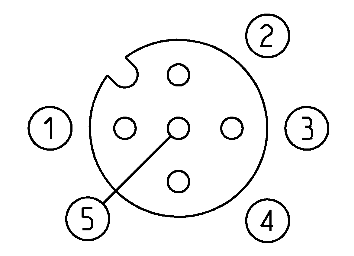
Ausgangsmodul, digital - Mod. ME3-0004-DL
Dieses digitale Ausgangsmodul wird an ein CPU-Modul oder ein Erweiterungsmodul angebaut und kann gemischt oder mit anderen Modulen I/O digital/analog sowie Anfangsmodulen des Zusatznetzes verbaut werden. Es verfügt über zwei 5-polige M12A-Steckdosen, jeweils geeignet für 2 digitale Ausgänge mit 10 W bei 24 V DC.
Es können beispielsweise 2x monostabile oder 1x bistabile Ventile pro Steckdose angeschlossen werden, oder aber andere elektrische Komponenten mit 10 W/24 V DC. Parallel und zeitgleich geschaltet, können so maximal 20 W bei 24 V DC angeschlossen werden.
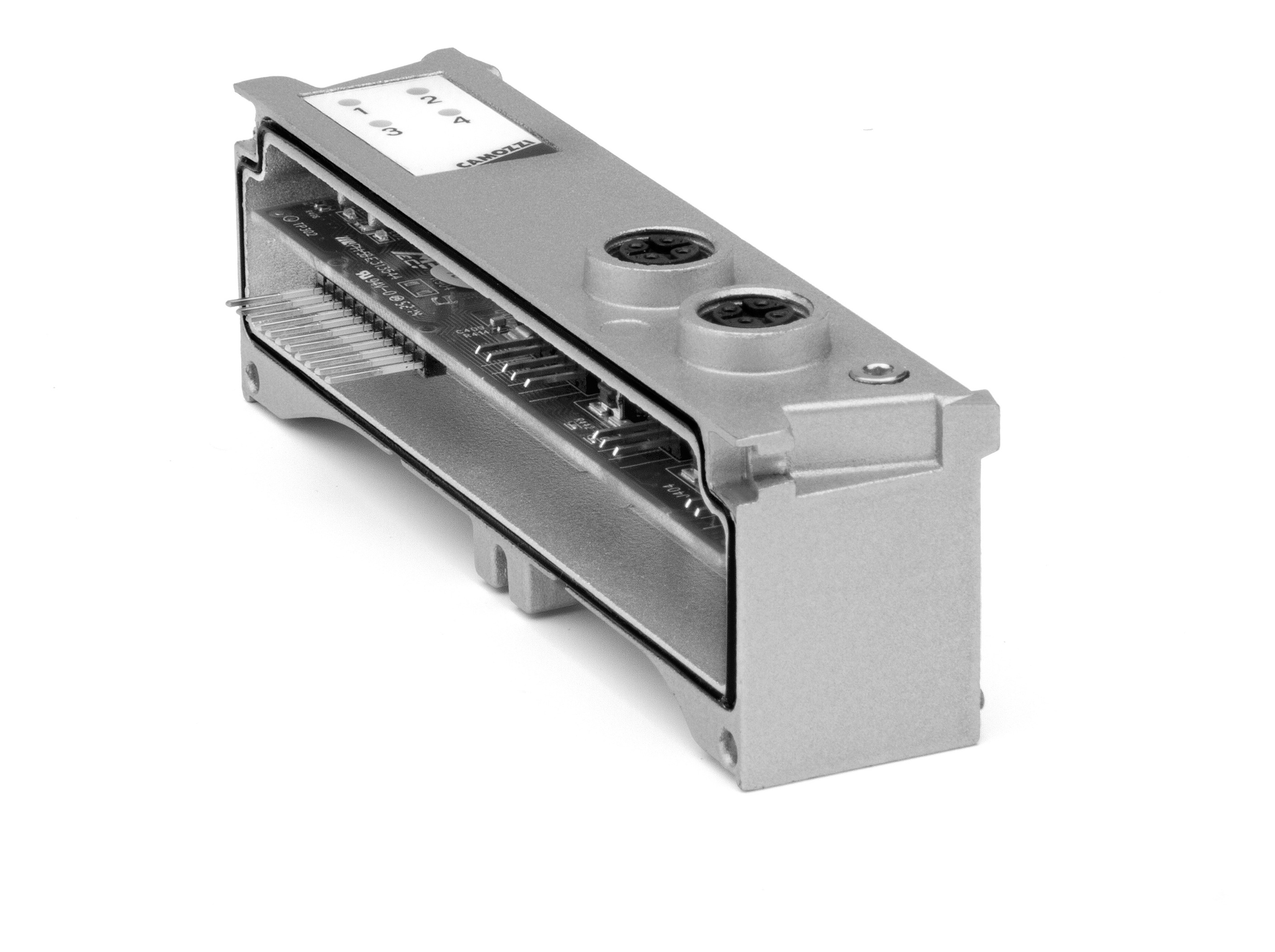
| Mod. | Modul- code | Ausgänge digital | Anschlussart | Anschlüsse | Abmessungen | LED | Spannung | Leistung max. M12-Stecker | Leistung max. digitale Ausgänge | Signaltyp | Schutzart | Betriebs- temperatur | Gewicht |
| ME3-0004-DL | Q | 4 | 5-polig M12A-Steckdose | 2 | 122 x 25 mm | 1 LED gelb/Ausgang | 24 V DC | 20 W | 10 W | NPN | IP65 | 0 ÷ 50°C | 100 g |


1-16/22 Ergebnisse


