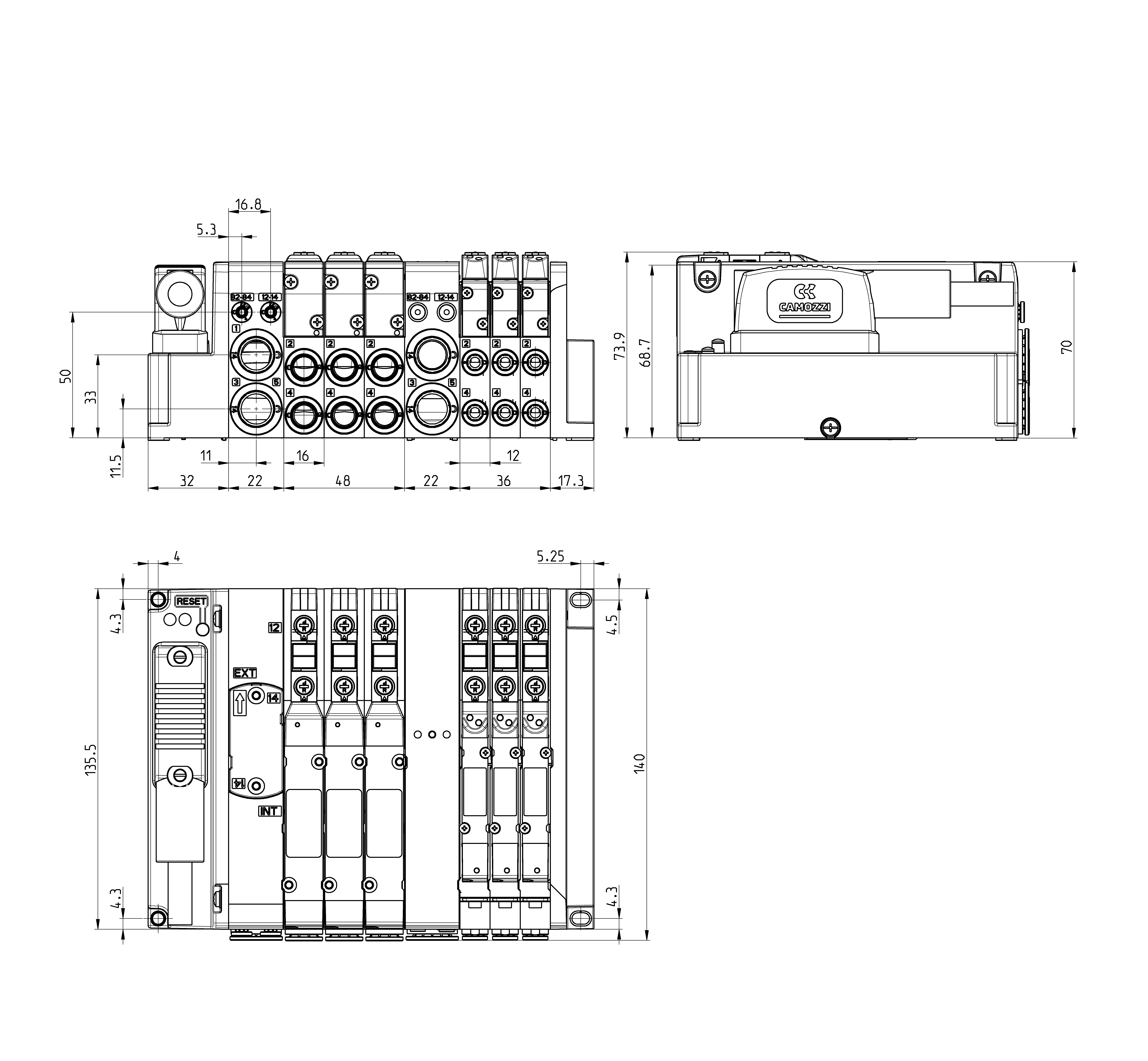
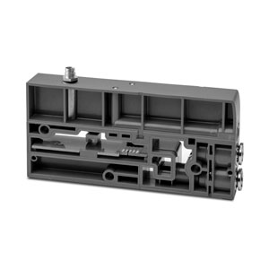
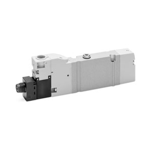
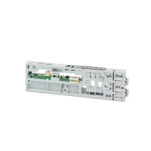
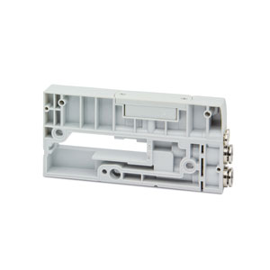
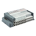
MULTIPOLE VERSION
Series D5
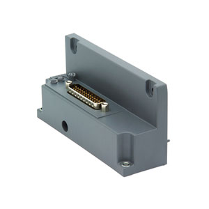
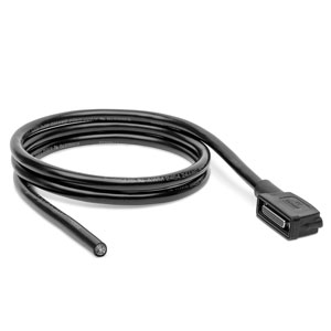
The multipole version can be connected quickly and safely through the connecting cable with angled outlet of 25 or 44 pins to the electric Sub-D connector integrated in the island. The single modularity of the subbases allows to create islands with up to a maximum of 11 or 19 valve positions according to the type of connecting cable used.
Series
Accessories
there are no salable codes online
If you have entered Filters, try changing them or look in the "Configurator" tab
there are no salable codes online
Look in the "Accessory" tab for the Configurator


addtocart.popup.message.success
The requested quantity is partially confirmed
Product {0} is already in your cart with quantity {1}. You can update the quantity from cart page.
Product is not active
The product could not be added to the cart due to insufficient stock
Quantity must be greater than zero
Min allowed quantity for product {0} is {1}
Max allowed quantity for product {0} is {1}
Pack size for product {0} is {1}
It is not possible to add the product with code {0} to this cart
An error occurred, please try again later or contact customer support
CODING EXAMPLE - MULTIPOLE VERSION
| DM | C | 5 | M | W | R | A | - | 15R | - | 2CD2NSHDN | - | 2MBLC2B | - | F | R |
| DM | MODULAR ISLAND | ||
| C |
VALVE C = VC Model |
||
| 5 |
SIZE 5 = 10,5mm (D1) + 16 mm (D2) |
||
| M |
ELECTRICAL CONNECTION M = Multipole 25 pin PNP Q = Multipole 44 pin PNP |
||
| W |
INTERFACE O = without interface W = WLAN |
||
| R |
MANUAL OVERRIDE P = push button R = with push and turn device |
||
| A |
SERVO-PILOT SUPPLY A = internal B = external |
||
| 15R |
CONNECTOR 0 = without connector CONNECTOR R WITH CABLE 03R = 3 mt 05R = 5 mt 10R = 10 mt 15R = 15 mt 20R = 20 mt 25R = 25 mt |
||
| 2CD2NSHDN |
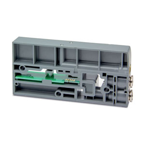
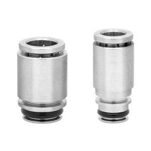
SUBBASES DIAPHRAGM Metric: N = cartridge tube Ø4 (D1) M = cartridge tube Ø6 (D1) B = cartridge tube Ø6 (D2) C = cartridge tube Ø8 (D2) D = cartridge tube Ø10 (D2) SUBBASE # Q = diaphragm on channels 1, 3, 5 R = diaphragm on channel 1 S = diaphragm on channels 3 and 5 WITH DIAPHRAGM AND EXTERNAL SERVO-PILOT SUPPLY # QT = diaphragm on channels 1, 3, 5; 12/14 external RT = diaphragm on channel 1; 12/14 external ST = diaphragm on channels 3, 5; 12/14 external WITH DIAPHRAGM AND INTEGRATED SILENCER # QH = diaphragm on channels 1, 3, 5 RH = diaphragm on channel 1 SH = diaphragm on channels 3, 5 SUBBASE FOR ADDITIONAL FLOW # X = supply (1) and exhausts (3, 5) XH = supply (1) and exhausts (3, 5) with integrated silencer INTERFACE SUBBASE FOR ADDITIONAL FLOW WITH EXTERNAL SERVO-PILOT SUPPLY # XT = additional supply (1) and exhausts (3, 5) FOR POWER SUPPLY # K = separation of power supply Z = separation of power supply - diaphragm on channel 1 # = these subbases are already provided with cartridges for tube Ø8, Ø5/16" |
Inches: N = cartridge tube Ø5/32” (D1) G = cartridge tube Ø1/4” (D1) L = cartridge tube Ø1/4” (D2) P = cartridge tube Ø3/8” (D2) C = cartridge tube Ø5/16” (D2) J = subbase (D5) for servo-pilot control through solenoid valve (E;F) * |
|
| 2MBLC2B |
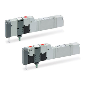
VALVES M = 5/2 monostable B = 5/2 bistable C = 2x3/2 NC A = 2x3/2 NO G = 2x3/2 (NC+NO) V = 5/3 CC K = 5/3 CO N = 5/3 CP L = free position W = position without valve |
E = 3/2 NC for internal servo-pilot control (Line 1) ** F = 3/2 NC for external servo-pilot control ** D = 2x2/2 NC H = 2x2/2 NO R = 1x2/2 NC + 1x2/2 NO |
|
| F |
TERMINAL PLATES Tube dimensions for port sizes 1, 3, 5 Metric: C = cartridge tube Ø8 D = cartridge tube Ø10 E = cartridge tube Ø12 F = cartridge tube Ø14 |
CS = cartridge tube Ø8 and external silencer (2939-8) DS = cartridge tube Ø10 and external silencer (2939-10) ES = cartridge tube Ø12 and external silencer (2939-12) |
Inches: C = cartridge tube Ø8, 5/16" CS = cartridge tube Ø8 (5/16"); and external silencer (2939-8) P = cartridge tube Ø3/8" R = cartridge tube Ø1/2" |
| R |
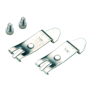
FIXING TYPE = direct R = DIN rail |
* = The subbase is equipped with a cartridge Ø4 (Ø5/32”).
** = Solenoid valve for subbase model J.
The choice of the cartridge made in the Terminal Plates section is also valid for the diaphragm and additional subbases.
QT, RT, ST, XT models have a 12/14 cartridge tube Ø4 (Ø5/32”).
** = Solenoid valve for subbase model J.
The choice of the cartridge made in the Terminal Plates section is also valid for the diaphragm and additional subbases.
QT, RT, ST, XT models have a 12/14 cartridge tube Ø4 (Ø5/32”).
1-10/10 results
1-8/8 results
 Sweden


 Download catalogue
