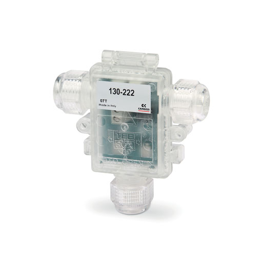
Electronic control device for proportional valves
Series 130
PWM control device, with current control system for directly operated proportional valves
Series 130 electronic control device allows to pilot any proportional valve with a maximun current of 1 A.
It turns a standard inlet signal (0-10V or 4-20 mA) into a PWM signal to obtain at the solenoid outlet a current which is proportional to the inlet signal.
A control system of the provided current allows to compensate variations due to heating of the solenoid or to the variation of the supply voltage. It is possible to adjust the maximum and minimum current provided to the solenoid. The outlet signal can have a ramp progress that is adjustable between 0 and 5 s. The device has a firmware dedicated to the proportional valve to pilot in order to guarantee the best performance.
Series
Accessories
there are no salable codes online
If you have entered Filters, try changing them or look in the "Configurator" tab
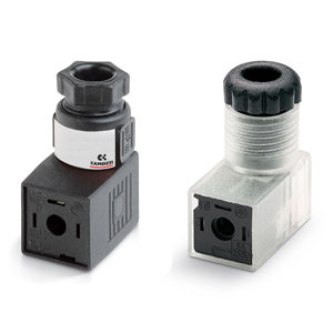
Connector - 125-800
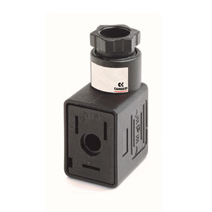
Connector din 43650 - 122-800


addtocart.popup.message.success
The requested quantity is partially confirmed
Product {0} is already in your cart with quantity {1}. You can update the quantity from cart page.
Product is not active
The product could not be added to the cart due to insufficient stock
Quantity must be greater than zero
Min allowed quantity for product {0} is {1}
Max allowed quantity for product {0} is {1}
Pack size for product {0} is {1}
It is not possible to add the product with code {0} to this cart
An error occurred, please try again later or contact customer support
| Material of container | Polycarbonate |
| Electrical connections | screw |
| Environmental temperature | 0 ÷ 50°C |
| Mounting | in any position |
| Power supply | 6 V ÷ 24 V DC (± 10%) |
| Consumption | 0.4 W (without valve) |
| Analogical input | 0 ÷ 10 V 4 ÷ 20 mA |
| Input impedence | >30 Kohm with inlet under voltage <200 ohm with inlet under current |
| Output PWM | 120 Hz ÷ 11.7 KHz (fixed, according to the valve chosen) |
| Maximum current (valve) | 1 A |
| Protection | Polarity inversion, short circuit of the outlet |
| External diameter of cable jacket | 5 ÷ 7.5 mm with seal only 4 ÷ 6 mm with reducer and seal |
| Conductor section | 26 ÷ 16 AWG / 0,13 ÷ 1,5 mm2 |
| Maximum length supply/signal cable | 10 m |
| Maximum length valve cable | 5 m |
| IP protection class according to EN 60529 | IP 54 |
| Ramp function | Adjustable time from 0 to 5 s |
| Regulation min. current (Offset) | 0% ÷ 40% F.S. |
| Regulation maximum current | 50% ÷ 100% F.S. |


addtocart.popup.message.success
The requested quantity is partially confirmed
Product {0} is already in your cart with quantity {1}. You can update the quantity from cart page.
Product is not active
The product could not be added to the cart due to insufficient stock
Quantity must be greater than zero
Min allowed quantity for product {0} is {1}
Max allowed quantity for product {0} is {1}
Pack size for product {0} is {1}
It is not possible to add the product with code {0} to this cart
An error occurred, please try again later or contact customer support
CODING EXAMPLE
| 130 | - | 2 | 2 | 2 |
| 130 | SERIES |
| 2 |
VOLTAGE 2 = 24 V DC (max power 24 W) 3 = 12 V DC (max power 12 W) 4 = 6 V DC (max power 6 W) 5 = 11 V DC (max power 11 W) |
| 2 |
POWER 1 = 3 W 2 = 6.5 W 3 = 3.2 W 4 = 4.3 W 5 = 10 W 6 = 4.2 W 7 = 2.5 W |
| 2 |
PWM FREQUENCY 2 = 500 Hz 3 = 1 KHz |
NOTE: it is possible to realize configurations with voltage, power and PWM frequency values that are not yet foreseen in the coding example.
For further information we suggest you to contact our technical department.
For further information we suggest you to contact our technical department.
| Mod. | Matching valve family | Valve voltage (Output) | Adjusted power | Adjusted frequency |
| 130-222 | Series AP - size 22 mm | 24 V DC | 6,5 W | 500 Hz |
| 130-322 | Series AP - size 22 mm | 12 V DC | 6,5 W | 500 Hz |
| 130-252 | Series AP - size 22 mm | 24 V DC | 10 W | 500 Hz |
| 130-352 | Series AP - size 22 mm | 12 V DC | 10 W | 500 Hz |
| 130-213 | Series AP - size 16 mm | 24 V DC | 3 W | 1000 Hz |
| 130-313 | Series AP - size 16 mm | 12 V DC | 3 W | 1000 Hz |
| 130-433 | Series CP - size 16 mm | 6 V DC | 3,2 W | 1000 Hz |
| 130-533 | Series CP - size 16 mm | 11 V DC | 3,2 W | 1000 Hz |
| 130-233 | Series CP - size 16 mm | 24 V DC | 3,2 W | 1000 Hz |
| 130-442 | Series CP - size 20 mm | 6 V DC | 4,3 W | 500 Hz |
| 130-342 | Series CP - size 20 mm | 12 V DC | 4,3 W | 500 Hz |
| 130-242 | Series CP - size 20 mm | 24 V DC | 4,3 W | 500 Hz |
| 130-463 | Series CP pressure compensated - size 20 mm | 6 V | 4,2 W | 1000 Hz |
| 130-363 | Series CP pressure compensated - size 20 mm | 12 V | 4,2 W | 1000 Hz |
| 130-263 | Series CP pressure compensated - size 20 mm | 24 V | 4,2 W | 1000 Hz |
| 130-473 | Series CP pressure compensated - size 16 mm | 6 V | 2,5 W | 1000 Hz |
| 130-373 | Series CP pressure compensated - size 16 mm | 12 V | 2,5 W | 1000 Hz |
| 130-273 | Series CP pressure compensated - size 16 mm | 24 V | 2,5 W | 1000 Hz |
 Brazil


 Download catalogue


