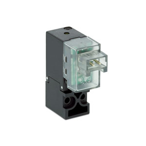
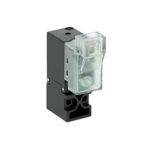
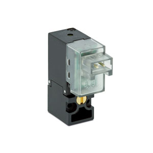
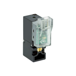
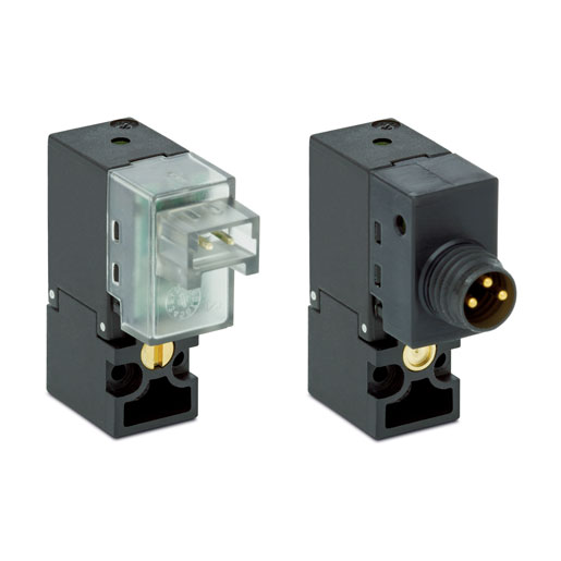
Électrovannes à commande directe
Série KL
2/2 - Normalement Fermé (NF)
3/2 - Normalement Fermé (NF) et Normalement Ouvert (NO)
3/2 - Universel (UNI)
3/2 - Normalement Fermé (NF) et Normalement Ouvert (NO)
3/2 - Universel (UNI)
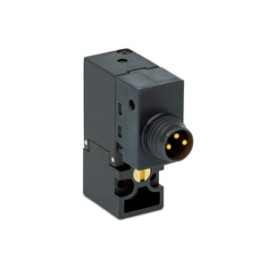
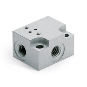
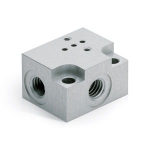
Series KL are miniaturised solenoid valves with a width of only 10 mm. The body is designed in such a way it can be mounted both on manifold and on subbase and the valve is available in 2-way normally closed and in 3-way normally closed, open and universal version. The use of a longer coil allowed to increase the pressure values the valves can withstand.
1-5/5 résultats
Séries
Accessoires
Il n'existe pas de codes vendables en ligne
Si vous avez saisi des filtres, essayez de les modifier ou consultez l'onglet "Configurateur".


addtocart.popup.message.success
La quantité demandée est partiellement confirmée
Le produit {0} est déjà dans votre panier avec la quantité {1}. Vous pouvez mettre à jour la quantité à partir de la page du panier.
Le produit n'est pas actif
Le produit n'a pas pu être ajouté à votre panier en raison d'un stock insuffisant.
La quantité doit être supérieure à zéro
La quantité minimale autorisée pour le produit {0} est {1}
La quantité maximale autorisée pour le produit {0} est {1}
Le conditionnement le produit {0} est {1}
Il n''est pas possible d''ajouter le produit avec le code {0} à votre panier.
Une erreur s'est produite, veuillez réessayer plus tard ou contacter le service client.
| CARACTÉRISTIQUES TECHNIQUES | |
| Fonction | 2/2 NC - 3/2 NC - 3/2 NO - 3/2 UNI |
| Fonctionnement | clapet à commande directe |
| Raccordements pneumatiques | sur embase |
| Diamètre de l’orifice | 0.6 ... 1.6 mm |
| Coefficient de débit kv (l/min) | 0.12 ... 0.50 |
| Pression de fonctionnement | 0 ÷ 3 ... 9 bar |
| Température de fonctionnement | 0 ÷ 50 °C |
| Fluide | air comprimé filtré, non lubrifié, selon ISO 8573-1 class 3.4.3, gaz inerte |
| Temps de réponse | ON <10 ms – OFF <10 ms |
| Commande manuelle | monostable ou bistable - seulement pour les version 3/2 |
| Installation | dans toutes les positions |
| MATÉRIAUX EN CONTACT AVEC LE FLUIDE | |
| Corps | PBT |
| Joints | FKM |
| Pièces internes | acier inoxydable - laiton |
| CARACTÉRISTIQUES ÉLECTRIQUES | |
| Tension | 6 ... 24 V DC - autres tensions sur demande |
| Tolérance de tension | ±10% |
| Consommation électrique | 1 W - 1.3/0.3 W - 4/1 W |
| Facteur de marche | ED 100% |
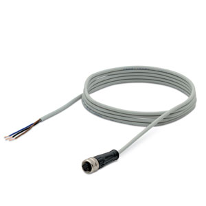
| Connexion électrique | connecteur mod. 121-8... - Connecteur M8 mod. CS... (la connexion M8 de la vanne supporte l’inversion de polarité) |
| Indice de protection | IP50 avec connecteur 121-8... - IP65 avec connecteur M8 |


addtocart.popup.message.success
La quantité demandée est partiellement confirmée
Le produit {0} est déjà dans votre panier avec la quantité {1}. Vous pouvez mettre à jour la quantité à partir de la page du panier.
Le produit n'est pas actif
Le produit n'a pas pu être ajouté à votre panier en raison d'un stock insuffisant.
La quantité doit être supérieure à zéro
La quantité minimale autorisée pour le produit {0} est {1}
La quantité maximale autorisée pour le produit {0} est {1}
Le conditionnement le produit {0} est {1}
Il n''est pas possible d''ajouter le produit avec le code {0} à votre panier.
Une erreur s'est produite, veuillez réessayer plus tard ou contacter le service client.
EXEMPLE DE CODIFICATION
| KL | 0 | 4 | 0 | A6 | 3 | A | Y | 1 | 3 | M |
| KL |
SÉRIE KL = standard KLE = extended |
| 0 |
CONCEPTION DU CORPS 0 = corps 3/2 - ISO 15218 A = corps 3/2 - ISO 15218 - bobine tournée de 180 2 = corps 2/2 body C = corps 2/2 body - bobine tournée de 180 |
| 4 |
NOMBRE DE VOIES - FONCTION 1 = 2/2-voies NC 4 = 3/2-voies NC 5 = 3/2-voies NO 6 = 3/2-voies UNI |
| 0 |
RACCORDEMENTS 0 = sur embase ou manifold |
| A6 |
DIAMÈTRE DE L’ORIFICE A6 = Ø 0.60 mm A8 = Ø 0.80 mm B1 = Ø 1.10 mm B2 = Ø 1.20 mm B3 = Ø 1.30 mm B6 = Ø 1.60 mm |
| 3 |
MATIÈRE DU JOINT 3 = FKM |
| A |
MATIÈRE DU CORPS A = PBT |
| Y |
COMMANDE MANUELLE 0 = non demandée ou non prévue Y = monostable B = bistable |
| 1 |
CONNEXION ÉLECTRIQUE 1 = Connexion à 90° avec protection et led B = connexion en ligne avec protection et led M = connexion M8 - 3 broches |
| 3 |
TENSION - CONSOMMATION ÉLECTRIQUE 1 = 6 V DC - 1 W 2 = 12 V DC - 1 W 3 = 24 VDC - 1 W A = 6 V DC - 1.3/0.3 W B = 12 V DC - 1.3/0.3 W C = 24 VDC - 1.3/0.3 W 5 = 5 V DC - 4/1 W 6 = 6 VDC - 4/1 W 7 = 12 V DC - 4/1 W 8 = 24 V DC - 4/1 W |
| M |
FIXATION M = vis de fixation pour métal P = vis de fixation pour plastique |
|
OPTIONS = standard OX1 = à utiliser avec de l’oxygène (résidu non volatil inférieur à 550 mg/m²) |
 France



 Télécharger le catalogue