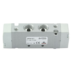
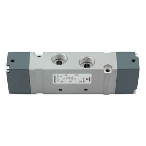
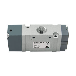
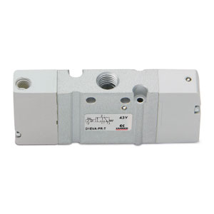
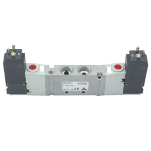
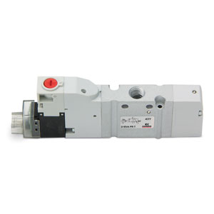
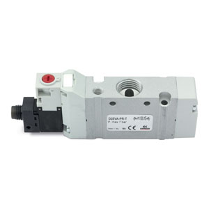
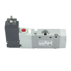
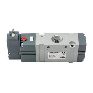
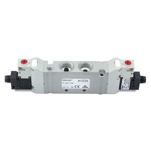
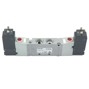
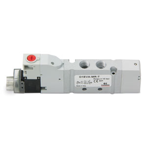
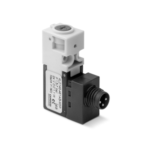
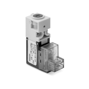
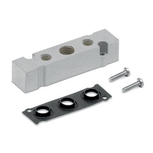
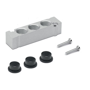
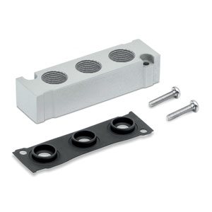
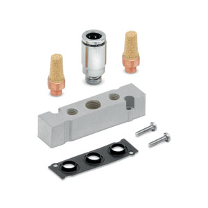
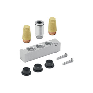
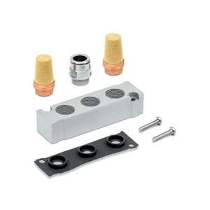
Series
Accessories
there are no salable codes online
If you have entered Filters, try changing them or look in the "Configurator" tab


addtocart.popup.message.success
Die angeforderte Menge ist teilweise bestätigt.
Das Produkt {0} befindet sich bereits mit der Menge {1} in Ihrem Warenkorb. Sie können die Menge auf der Seite "Warenkorb" aktualisieren.
Das Produkt ist nicht aktiv.
Das Produkt konnte nicht in den Warenkorb gelegt werden, da es nicht vorrätig ist.
Die Menge muss größer Null sein.
Die zulässige Mindestmenge für das Produkt {0} ist {1}.
Die maximal zulässige Menge für Produkt {0} ist {1}.
Die Verpackungseinheit für Produkt {0} ist {1}.
Es ist nicht möglich, das Produkt mit dem Code {0} in den Warenkorb zu legen.
Es ist ein Fehler aufgetreten, bitte versuchen Sie es später noch einmal oder wenden Sie sich an den Kundenservice.
MODELLBEZEICHNUNG
| DC | A | 1 | 0 | - | 12 |
| DC | SERIES |
| A |
REIHENGRUNDPLATTE A = für Muffenventil, Einzelanschluss (Version VA) |
| 1 |
BAUBREITE 1 = 10,5 mm 2 = 16 mm 4 = 25 mm |
| 0 |
VENTILKÖRPER 0 = für Grundplattenmontage |
| 12 |
ANZAHL VENTILPOSITIONEN 2 3 4 ... 16 17 (no D4) 18 (no D4) 19 (no D4) |
MODELLBEZEICHNUNG REIHENGRUNDPLATTE MIT VENTILEN UND STECKANSCHLÜSSEN
| DC | A | 1 | E | P | MBMXCVB | 3BX2AB | CSL | R |
| DC | SERIES |
| A |
MANIFOLD WITH VALVES A = For type VA valve |
| 1 |
SIZE/DIMENSION 1 = 10.5 mm 2 = 16 mm 4 = 25 mm |
| E |
ACTUATION E = Electric (D1 and D2) 3 = Electric with solenoid 15 mm (D2 and D4) C = Electric with M8 connector (D1 and D2) P = Pneumatic |
| P |
TYPE OF MANUAL OVERRIDE P = push button (not for "3" actuation) R = with push and turn device 0 = without manual override (for "P" actuation) |
| MBMXCVB |
TYPE OF VALVE / SOLENOID VALVE M = 5/2 Monostable B = 5/2 Bistable C = 2 x 3/2 NC A = 2 x 3/2 NO G = 2 x 3/2 (NC + NO) V = 5/3 CC K = 5/3 CO N = 5/3 CP L= Free position X = Additional supply and exhaust Y = Additional supply and exhaust with silencer SOLENOID VALVE WITH EXTERNAL SERVO-PILOT SUPPLY MZ = 5/2 Monostable BZ = 5/2 Bistable CZ = 2 x 3/2 NC AZ = A = 2 x 3/2 NO GZ = 2 x 3/2 (NC + NO) VZ = 5/3 CC KZ = 5/3 CO NZ = 5/3 CP |
| 3BX2AB |
CONNECTIONS ON VALVE POSITIONS T = Thread A = Ø4 (D1) Fittings 6512 4-M7-M B = Ø6 (D1) Fittings 6512 6-M7-M C = Ø8 (D2) Fittings S6510 8-1/4 (D2) S6510 6-1/4 D = Ø10 (D2) Fittings 6512 10-1/4-M E = Ø12 (D4) Fittings S6510 12-3/8 (D4) S6510 10-3/8 F = Ø14 (D4) Fittings S6510 14-3/8 L = Free position X = Threaded plate Y = See code D1AVA-Y / D2AVA-Y / D4AVA-Y The pneumatically operated solenoid valves with external servo-pilot supply with connections from A to F are already equipped with fittings on the pilot ports Ø4 (D1 and D2) 6512 4 – M5 Ø6 (D4) 6512 6 – M5 |
| CSL |
MANIFOLD CONNECTIONS T = Thread (on both sides) C = Fittings on connections 1;3;5 CS = Fittings Ø 8 - Silencer 2931 1/8 on supply + silencers on exhausts D = Fittings Ø 10 on connections 1;3;5 DS = Fittings Ø 10 on supply + silencers on exhausts E = Fittings Ø 12 on connections 1;3;5 ES = Fittings Ø 12 on supply + silencers on exhausts F = Fittings Ø 14 on connections 1;3;5 FS = Fittings Ø 14 on supply + silencers on exhausts G = Fittings Ø 16 (D4), S6510 16-1/2 GS = Fittings Ø 16 on supply + silencers on exhausts CONNECTION SIDE = Both L = Fittings on the Left (right side covered) R = Fittings on the Right (left side covered) (D1) 6512 8-1/8-M (D1) 6512 8-1/8-M + 2921 1/8 (D2) S6510 10-3/8 (D2) S6510 10-3/8 + 2921 3/8 (D2) S6510 12 3/8 (D2) S6510 12 3/8 + 2921 3/8 (D4) S6510 14-1/2 (D4) S6510 14-1/2 + 2921 1/2 (D4) S6510 16-1/2 (D4) S6510 16-1/2 + 2921 1/2 (D2) S6510 8-3/8 (D2) S6510 8-3/8 + 2921 3/8 (D4) S6510 10-1/2 (D4) S6510 10-1/2 + 2921 1/2 (D4) S6510 12-1/2 (D4) S6510 12-1/2 + 2921 1/2 |
| R |
FIXING: = Direct R = Port for DIN rail (only for D1) |
|
In case of the same consecutive codes, group them and indicate the total quantity, for example: DCA1EP-MMMYCCVG-BBBYBAAA-CSL-R DCA1EP-3MY2CVG-3BYB3A-CSL-R VERSION 3, through the connector with rectifier bridge, can be used for AC applications. (see the connectors at the end of the section) |
MODELLBEZEICHNUNG
| D | 1 | E | VA | - | B | P | - | BS |
| D | SERIE | |
| 1 |
BAUBREITE 1 = 10,5 mm 2 = 16 mm 4 = 25 mm |
|
| E |
BETÄTIGUNG E = elektrisch (D1 und D2) 3 = elektrisch mit Spule 15 mm (D2 und D4) C = elektrisch mit M8-Stecker (D1 und D2) P = pneumatisch |
|
| VA |
KOMPONENTE VA = Muffenventil, Einzelanschluss |
|
| B |
FUNKTION M = 5/2 monostabil B = 5/2 bistabil P = 3/2 NC Q = 3/2 NO C = 2x3/2 NC A = 2x3/2 NO G = 2x3/2 (NC+NO) N = 5/3 Mitte belüftet V = 5/3 Mitte geschlossen K = 5/3 Mitte entlüftet |
VERSION MIT EXTERNER VORSTEUERUNG MZ = 5/2 monostabil BZ = 5/2 bistabil PZ = 3/2 NC QZ = 3/2 NO CZ = 2 x 3/2 NC AZ = 2 x 3/2 NO GZ = 2 x 3/2 (NC+NO) NZ = 5/3 Mitte belüftet VZ = 5/3 Mitte geschlossen KZ = 5/3 Mitte entlüftet |
| P |
HANDHILFSBETÄTIGUNG P = monostabil (nicht für D4) R = monostabil mit Verriegelungsmöglichkeit 0 = ohne (für Betätigung “P”) |
|
| BS |
ANSCHLUSS T = Gewinde A = Steckanschluss Ø4 mm (D1) 6512 4-M7-M B = Steckanschluss Ø6 mm (D1) 6512 6-M7-M Steckanschluss Ø6 mm (D2) S6510 6-1/4 C = Steckanschluss Ø8 mm (D2) S6510 8-1/4-M D = Steckanschluss Ø10 mm (D4) 6512 10-1/4-M Steckanschluss Ø10 mm (D4 S6510 10-3/8 E = Steckanschluss Ø12 mm (D4) S6510 12-3/8 F = Steckanschluss Ø14 mm (D4) S6510 14-3/8 |
AS = Steckanschluss Ø4 mm (D1) 6512 4-M7-M + Schalldämpfer 2931 M7 BS = Steckanschluss Ø6 mm (D1) 6512 6-M7-M + Schalldämpfer 2931 M7 Steckanschluss Ø6 mm (D2) S6510 6-1/4 + 2921 1/4 CS = Steckanschluss Ø8 mm (D2) S6510 8-1/4-M + Schalldämpfer 2921 1/4 DS = Steckanschluss Ø10 mm (D2) 6512 10-1/4-M + Schalldämpfer 2921 1/4 Steckanschluss Ø10 mm S6510 10-3/8 + 2921 3/8 ES = Steckanschluss Ø12 mm (D4) S6510 12-3/8 + Schalldämpfer 2931 3/8 FS = Steckanschluss Ø14 mm (D4) S6510 14-3/8 + Schalldämpfer 2931 3/8 |
|
BETÄTIGUNG 3: Bei einer Anwendung mit Wechselstrom eine Gerätesteckdose mit integrierter Gleichrichterbrücke verwenden. |
1-16/37 Ergebnisse
1-16/18 Ergebnisse
 Ungarn



 Katalog herunterladen