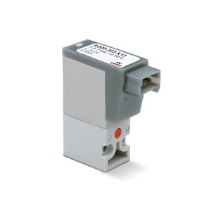
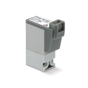
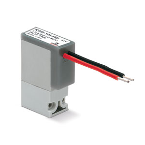
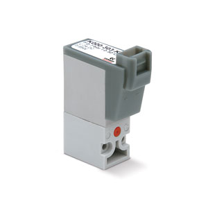
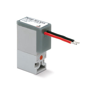
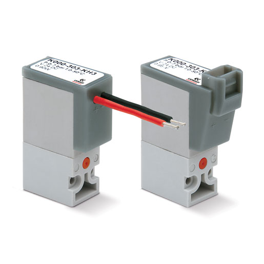
Direct acting solenoid valves
Series K
2/2-way - Normally Closed (NC)
3/2-way - Normally Closed (NC) and Normally Open (NO)
3/2-way - Normally Closed (NC) and Normally Open (NO)
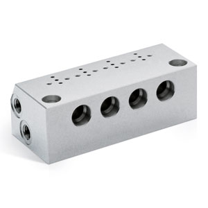
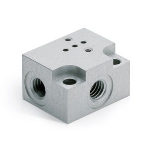
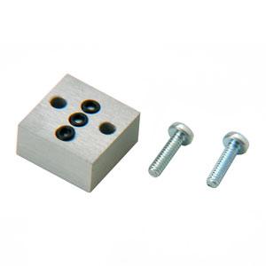
The Series K direct acting solenoid valves can be mounted on single sub-bases or manifolds.
Thanks to the same mounting pad 2/2-way and 3/2-way versions can be installed on the same manifold.
The manual override is available only for the 3/2-way versions.
Thanks to the same mounting pad 2/2-way and 3/2-way versions can be installed on the same manifold.
The manual override is available only for the 3/2-way versions.
1-9/9 results
Series
Accessories
there are no salable codes online
If you have entered Filters, try changing them or look in the "Configurator" tab
there are no salable codes online
Look in the "Accessory" tab for the Configurator


addtocart.popup.message.success
The requested quantity is partially confirmed
Product {0} is already in your cart with quantity {1}. You can update the quantity from cart page.
Product is not active
The product could not be added to the cart due to insufficient stock
Quantity must be greater than zero
Min allowed quantity for product {0} is {1}
Max allowed quantity for product {0} is {1}
Pack size for product {0} is {1}
It is not possible to add the product with code {0} to this cart
An error occurred, please try again later or contact customer support
| TECHNICAL FEATURES | |
| Function | 2/2 NC - 3/2 NC - 3/2 NO |
| Operation | direct acting poppet type |
| Pneumatic connections | on subbase |
| Orifice diameter | 0.6 ... 1 mm |
| Flow coefficient kv (l/min) | 0.12 ... 0.30 |
| Operating pressure | 0 ÷ 3 ... 7 bar |
| Operating temperature | 0 ÷ 50 °C |
| Fluid | filtered compressed air, unlubricated, according to ISO 8573-1:2010 class [3:4:3], inert gas |
| Response time | ON <10 ms – OFF <10 ms |
| Manual override | monostable - only for 3/2 versions |
| Installation | in any position |
| MATERIALS IN CONTACT WITH THE MEDIUM | |
| Body | PBT |
| Seals | NBR - FKM |
| Internal parts | stainless steel |
| ELECTRICAL FEATURES | |
| Voltage | 6 ... 24 V DC - other voltages on demand |
| Voltage tolerance | ±10% |
| Power consumption | 1 W |
| Duty cycle | ED 100% |
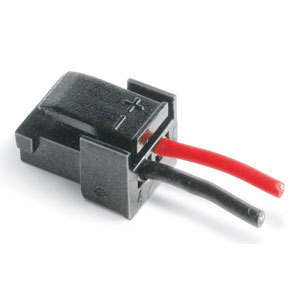
| Electrical connection | connector mod. 121-8... - 300 mm flying leads |
| Protection class | IP50 |
| Special versions available on demand |
1-9/9 results
CODING EXAMPLE
| K | 0 | 00 | 3 | 0 | 3 | K | 2 | 3 |
| K | SERIES | ||
| 0 |
BODY DESIGN 0 = single sub-base (only M5) or interface 1 = manifold |
||
| 00 |
NUMBER OF POSITIONS 00 = interface 01 = single base (only M5) 02 ÷ 99 = manifold number of positions |
||
| 3 |
NUWAYS - FUNCTMBER OF IONS 0 = manifold or single base 1 = 2/2-way - NC 2 = 2/2-way - NC electric part revolved by 180° |
3 = 3/2-way - NC 5 = 3/2-way - NC electric part revolved by 180° |
4 = 3/2-way - NO 6 = 3/2-way - NO electric part revolved by 180° |
| 0 |
PORTS: 0 = on subbase or manifold 2 = M5 side outlets |
||
| 3 |
ORIFICE DIAMETER 2 = Ø 0.6 mm 3 = Ø 0.8 mm 5 = Ø 1.0 mm |
||
| K |
MATERIALS F = PBT body - FKM poppet seal K = PBT body - HNBR poppet seal (only for 3/2-way versions) |
||
| 2 |
ELECTRICAL CONNECTION 1 = 90° connection with protection and led 2 = 90° connection with protection 3 = 90° connection |
B = in-line connection with protection and led C = in-line connection with protection D = in-line connection |
F = 300 mm flying leads with protection and led G = 300 mm flying leads with protection H = 300 mm flying leads |
| 3 |
VOLTAGE - POWER CONSUMPTION 1 = 6V DC - 1W 2 = 12V DC - 1W 3 = 24V DC - 1W |
||
|
FIXING = fixing screws for plastic M = fixing screws for metal |
|||
|
OPTIONS = standard OX1 = for use with oxygen (non volatile residual less than 550 mg/m²) OX2 = for use with oxygen (non volatile residual less than 33 mg/m²) |
 United States



 Download catalogue