 United States


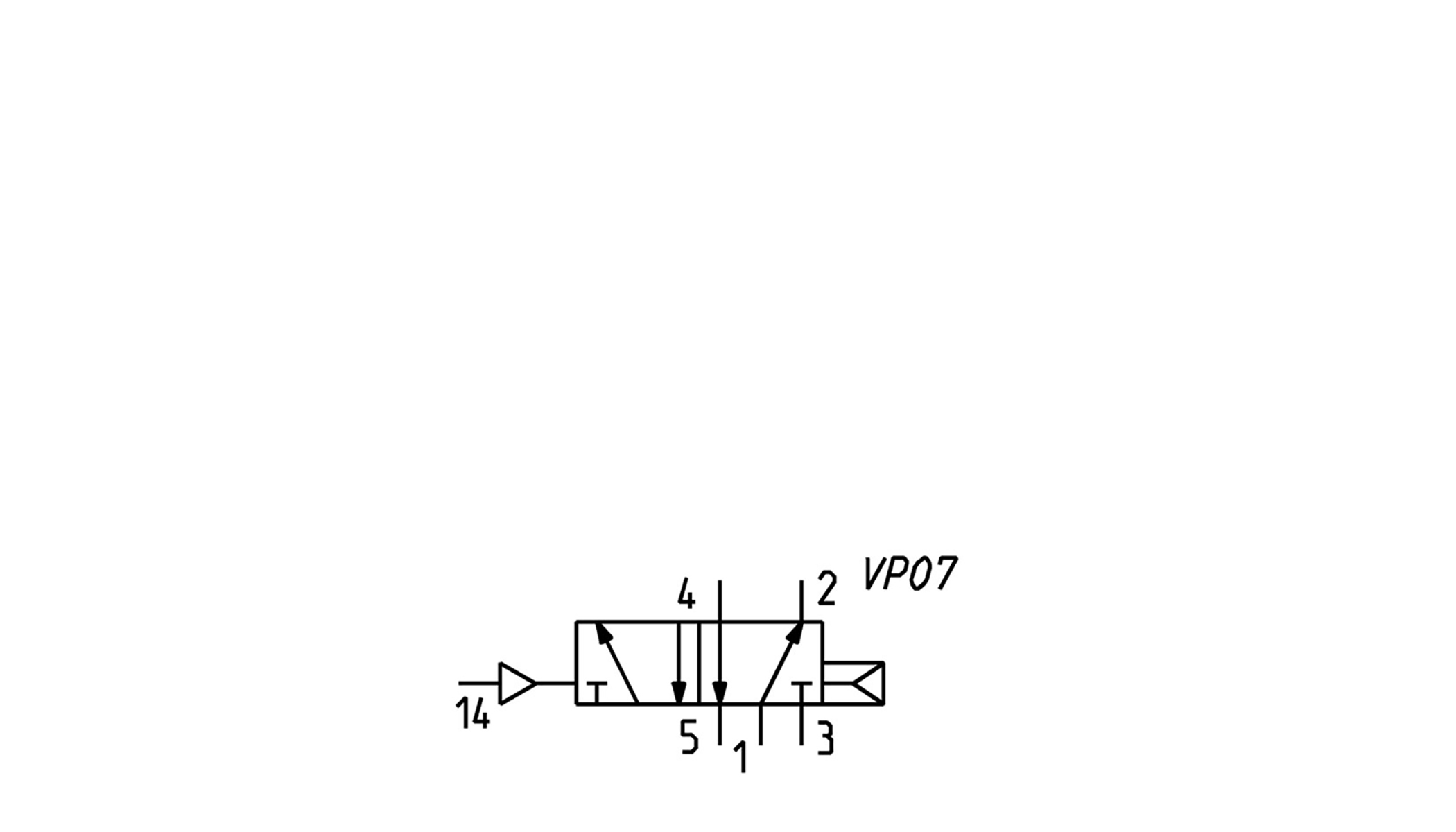
5/2-way pneumatically operated valve, monostable - size 10,5
Series D1-VA
N.B. the pilot pressure should never be lower than the operating pressure.
 Download catalogue
Series
Accessories
there are no salable codes online
If you have entered Filters, try changing them or look in the "Configurator" tab
there are no salable codes online
Look in the "Accessory" tab for the Configurator


Quantity added:
addtocart.popup.message.success
The requested quantity is partially confirmed
Product {0} is already in your cart with quantity {1}. You can update the quantity from cart page.
Product is not active
The product could not be added to the cart due to insufficient stock
Quantity must be greater than zero
Min allowed quantity for product {0} is {1}
Max allowed quantity for product {0} is {1}
Pack size for product {0} is {1}
It is not possible to add the product with code {0} to this cart
An error occurred, please try again later or contact customer support

Full screen

Quantity added:
addtocart.popup.message.success
The requested quantity is partially confirmed
Product {0} is already in your cart with quantity {1}. You can update the quantity from cart page.
Product is not active
The product could not be added to the cart due to insufficient stock
Quantity must be greater than zero
Min allowed quantity for product {0} is {1}
Max allowed quantity for product {0} is {1}
Pack size for product {0} is {1}
It is not possible to add the product with code {0} to this cart
An error occurred, please try again later or contact customer support
CODING EXAMPLE
| D | 1 | E | VA | B | P | BS |
| D | SERIES |
| 1 |
SIZE: 1 = 10.5 mm 2 = 16 mm 4 = 25 mm |
| E |
ACTUATION: E = electric (D1 and D2) 3 = electric 15 mm (D2 and D4) C = electric with M8 connections (D1 and D2) P = pneumatic |
| VA |
COMPONENT: VA = Valve with threaded body |
| B |
TYPE OF SOLENOID VALVE: M = 5/2 Monostable B = 5/2 Bistable P = 3/2 NC Q = 3/2 NO C = 2 x 3/2 NC A = 2 x 3/2 NO G = 2 x 3/2 (NC+NO) N = 5/3 CP V = 5/3 CC K = 5/3 CO SOLENOID VALVE WITH EXTERNAL SERVO-PILOT SUPPLY MZ = 5/2 Monostabile BZ = 5/2 Bistabile PZ = 3/2 NC QZ = 3/2 NO CZ = 2 x 3/2 NC AZ = 2 x 3/2 NO GZ = 2 x 3/2 (NC+NO) NZ = 5/3 CP VZ = 5/3 CC KZ = 5/3 CO |
| P |
TYPE OF MANUAL OVERRIDE: P = push button (not for D4) R = with push and turn device 0 = for P actuation |
| BS |
CONNECTIONS: T = Thread A = Ø4 (D1) fittings 6512 4-M7-M B = Ø6 (D1) fittings 6512 6-M7-M Ø6 (D2) S6510 6-1/4 C = Ø8 (D2) fittings 6510 8-1/4 D = Ø10 (D4) fittings 6512 10-1/4-M Ø10 (D4) S6510 10-3/8 E = Ø12 (D4) fittings 6510 12-3/8 F = Ø14 (D4) fittings 6510 14-3/8 AS = Ø4 (D1) fittings 6512 4-M7-M + silencers 2931 M7 BS = Ø6 (D1) fittings 6512 6-M7-M + silencers 2931 M7 Ø6 (D2) S6510 6-1/4 + 2921 1/4 CS = Ø8 (D2) fittings S6510 8-1/4-M + silencers 2921 1/4 DS = Ø10 (D2) fittings 6512 10-1/4-M + silencers 2921 1/4 Ø10 S6510 10-3/8 + 2921 3/8 ES = Ø12 (D4) fittings S6510 12-3/8 + silencers 2931 3/8 FS = Ø14 (D4) fittings S6510 14-3/8 + silencers 2931 3/8 The pneumatically operated solenoid valves with external servo-pilot supply with connections from A to F are already equipped with fittings on the pilot ports Ø4 (D1 and D2) 6512 4 – M5 Ø6 (D4) 6512 6 – M5 |
| VERSION 3, through the connector with rectifier bridge 125-571-3, can be used for AC applications. (see the connectors at the end of the section) |
CODING EXAMPLE
| DC | A | 1 | 0 | 12 |
| DC | SERIES |
| A |
MANIFOLD A = For type VA valves |
| 1 |
SIZE 1 = 10.5 mm 2 = 16 mm 4 = 25 mm |
| 0 |
BODY TYPE 0 = body for sub-base assembly |
| 12 |
N° OF POSITIONS 2 3 4 ... 16 17 (no D4) 18 (no D4) 19 (no D4) |
CODING EXAMPLE MANIFOLD WITH VALVES AND FITTINGS
| DC | A | 1 | E | P | MBMXCVB | 3BX2AB | CSL | R |
| DC | SERIES |
| A |
MANIFOLD WITH VALVES A = For type VA valve |
| 1 |
SIZE/DIMENSION 1 = 10.5 mm 2 = 16 mm 4 = 25 mm |
| E |
ACTUATION E = Electric (D1 and D2) 3 = Electric with solenoid 15 mm (D2 and D4) C = Electric with M8 connector (D1 and D2) P = Pneumatic |
| P |
TYPE OF MANUAL OVERRIDE P = push button (not for "3" actuation) R = with push and turn device 0 = without manual override (for "P" actuation) |
| MBMXCVB |
TYPE OF VALVE / SOLENOID VALVE M = 5/2 Monostable B = 5/2 Bistable C = 2 x 3/2 NC A = 2 x 3/2 NO G = 2 x 3/2 (NC + NO) V = 5/3 CC K = 5/3 CO N = 5/3 CP L= Free position X = Additional supply and exhaust Y = Additional supply and exhaust with silencer SOLENOID VALVE WITH EXTERNAL SERVO-PILOT SUPPLY MZ = 5/2 Monostable BZ = 5/2 Bistable CZ = 2 x 3/2 NC AZ = A = 2 x 3/2 NO GZ = 2 x 3/2 (NC + NO) VZ = 5/3 CC KZ = 5/3 CO NZ = 5/3 CP |
| 3BX2AB |
CONNECTIONS ON VALVE POSITIONS T = Thread A = Ø4 (D1) Fittings 6512 4-M7-M B = Ø6 (D1) Fittings 6512 6-M7-M C = Ø8 (D2) Fittings S6510 8-1/4 (D2) S6510 6-1/4 D = Ø10 (D2) Fittings 6512 10-1/4-M E = Ø12 (D4) Fittings S6510 12-3/8 (D4) S6510 10-3/8 F = Ø14 (D4) Fittings S6510 14-3/8 L = Free position X = Threaded plate Y = See code D1AVA-Y / D2AVA-Y / D4AVA-Y The pneumatically operated solenoid valves with external servo-pilot supply with connections from A to F are already equipped with fittings on the pilot ports Ø4 (D1 and D2) 6512 4 – M5 Ø6 (D4) 6512 6 – M5 |
| CSL |
MANIFOLD CONNECTIONS T = Thread (on both sides) C = Fittings on connections 1;3;5 CS = Fittings Ø 8 - Silencer 2931 1/8 on supply + silencers on exhausts D = Fittings Ø 10 on connections 1;3;5 DS = Fittings Ø 10 on supply + silencers on exhausts E = Fittings Ø 12 on connections 1;3;5 ES = Fittings Ø 12 on supply + silencers on exhausts F = Fittings Ø 14 on connections 1;3;5 FS = Fittings Ø 14 on supply + silencers on exhausts G = Fittings Ø 16 (D4), S6510 16-1/2 GS = Fittings Ø 16 on supply + silencers on exhausts CONNECTION SIDE = Both L = Fittings on the Left (right side covered) R = Fittings on the Right (left side covered) (D1) 6512 8-1/8-M (D1) 6512 8-1/8-M + 2921 1/8 (D2) S6510 10-3/8 (D2) S6510 10-3/8 + 2921 3/8 (D2) S6510 12 3/8 (D2) S6510 12 3/8 + 2921 3/8 (D4) S6510 14-1/2 (D4) S6510 14-1/2 + 2921 1/2 (D4) S6510 16-1/2 (D4) S6510 16-1/2 + 2921 1/2 (D2) S6510 8-3/8 (D2) S6510 8-3/8 + 2921 3/8 (D4) S6510 10-1/2 (D4) S6510 10-1/2 + 2921 1/2 (D4) S6510 12-1/2 (D4) S6510 12-1/2 + 2921 1/2 |
| R |
FIXING: = Direct R = Port for DIN rail (only for D1) |
|
In case of the same consecutive codes, group them and indicate the total quantity, for example: DCA1EP-MMMYCCVG-BBBYBAAA-CSL-R DCA1EP-3MY2CVG-3BYB3A-CSL-R VERSION 3, through the connector with rectifier bridge, can be used for AC applications. (see the connectors at the end of the section) |
5/2-way pneumatically operated valve, monostable - size 10,5
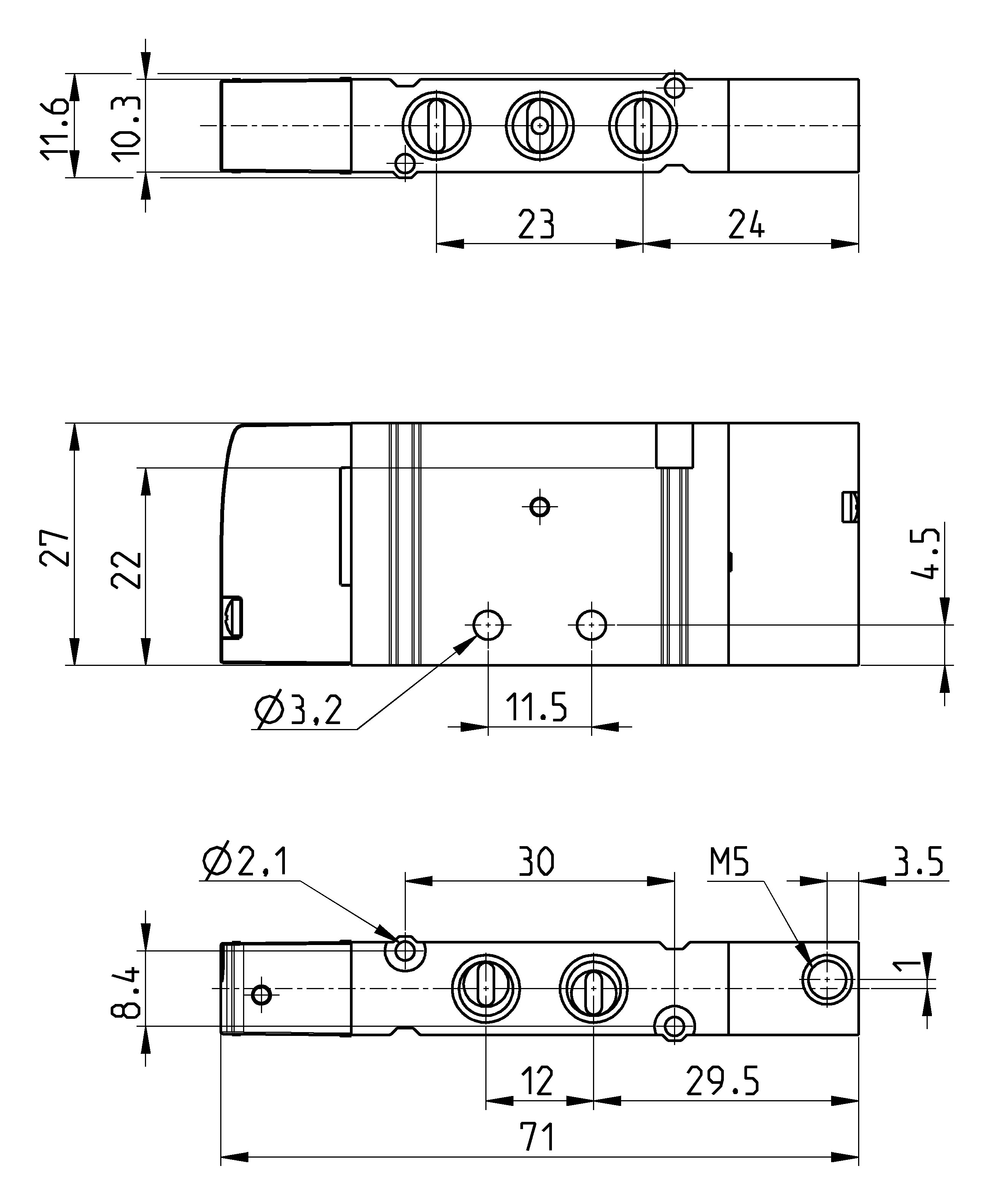
| Mod. | Ports | Pilot supply | Pilot supply pressure (bar) | Operating pressure (bar) | Flow (Nl/min) |
| D1PVA-M0-T | M7 | M5 | 2.5 ÷ 10 | 2.5 ÷ 10 | 270 |

1-16/18 results


