 United States


Electromechanical cylinders
Series 6E
Sizes 32, 40, 50, 63, 80, 100
The Series 6E cylinders are mechanical linear actuators with rod, in which the rotary movement, generated by a motor, is converted into a linear movement by means of a recirculating ball screw. Available in 6 sizes, the Series 6E has dimensions based on the ISO 15552 standard and it is therefore possible to use the mounting accessories of the pneumatic cylinders.
The cylinders are equipped with a magnet that makes it possible to use external magnetic proximity switches (Series CST and CSH), allowing operations like homing or extra-stroke readings to be performed. The Series 6E is equipped with specific interface kits, which make it possible to connect the motor, both in line and parallel. High precision and easy mounting make the Series 6E the ideal solution for different applications, especially for multi-position systems.
The cylinders are equipped with a magnet that makes it possible to use external magnetic proximity switches (Series CST and CSH), allowing operations like homing or extra-stroke readings to be performed. The Series 6E is equipped with specific interface kits, which make it possible to connect the motor, both in line and parallel. High precision and easy mounting make the Series 6E the ideal solution for different applications, especially for multi-position systems.
 Download catalogue
Series
Accessories
there are no salable codes online
If you have entered Filters, try changing them or look in the "Configurator" tab
there are no salable codes online
Look in the "Accessory" tab for the Configurator


Quantity added:
addtocart.popup.message.success
The requested quantity is partially confirmed
Product {0} is already in your cart with quantity {1}. You can update the quantity from cart page.
Product is not active
The product could not be added to the cart due to insufficient stock
Quantity must be greater than zero
Min allowed quantity for product {0} is {1}
Max allowed quantity for product {0} is {1}
Pack size for product {0} is {1}
It is not possible to add the product with code {0} to this cart
An error occurred, please try again later or contact customer support
| Construction | electromechanical cylinder with recirculating ball screw |
| Design | profile with thread rolling screws based on the ISO 15552 standard |
| Operation | multi-position actuator with high precision linear movement |
| Sizes | 32, 40, 50, 63, 80, 100 |
| Strokes min - max | 100 ÷ 1500 mm |
| Anti-rotation function | with anti-friction pads in technopolymer |
| Mounting | front / rear flange, with feet, with front / rear / swivel trunnion |
| Mounting motor | in line and parallel |
| Operating temperature | 0°C ÷ 50°C |
| Storage temperature | -20°C ÷ 80°C |
| Protection class | IP40 / IP65 |
| Lubrication | Not necessary. A pre-lubrication is performed on the cylinder. |
| Max. Reversing backlash | 0,02 mm |
| Repeatability | ± 0,02 |
| Duty cycle | 100% |
| Max rotation play | ± 0,4° |
| Use with external sensors | slots on three sides for sensors model CSH and CST |

Full screen

Quantity added:
addtocart.popup.message.success
The requested quantity is partially confirmed
Product {0} is already in your cart with quantity {1}. You can update the quantity from cart page.
Product is not active
The product could not be added to the cart due to insufficient stock
Quantity must be greater than zero
Min allowed quantity for product {0} is {1}
Max allowed quantity for product {0} is {1}
Pack size for product {0} is {1}
It is not possible to add the product with code {0} to this cart
An error occurred, please try again later or contact customer support
CODING EXAMPLE
| 6E | 032 | BS | 0200 | P05 | A |
| 6E | SERIES | |
| 032 |
SIZE 032 = 32 040 = 40 050 = 50 |
063 = 63 080 = 80 100 = 100 |
| BS |
TRANSMISSION BS = recirculating ball screw |
|
| 0200 |
STROKE 100 ÷ 1500 mm |
|
| P05 |
SCREW PITCH P05 = 5 mm P10 = 10 mm P16 = 16 mm (for size 40 only) P20 = 20 mm (for size 50 only) |
P25 = 25 mm (for size 63 only) P32 = 32 mm (for size 80 only) P40 = 40 mm (for size 100 only) |
| A |
CONSTRUCTION A = standard with rod nut |
|
|
VERSION = IP40 (not available for sizes 80 and 100) P = IP65 ( _ _ _ ) = extended piston rod _ _ _ mm |
GUIDE MOD.45NUT, 45NHT, 45NHB
| 45 | N | UT | 050 | A | 0100 |
| 45 | SERIES |
| N |
VERSION N = standard |
| UT |
OPERATION UT = "U" self lubricating guide HT = "H" self lubricating guide HB = "H" ball guide |
| 050 |
SIZE 032 = 32 040 = 40 050 = 50 063 = 63 |
| A |
MATERIALS A = anodized aluminium body - stainless steel AISI 420B columns for 45UT and 45HT - hardened steel C50 columns for 45HB |
| 0100 | STROKE in mm |
GUIDE MOD. 6ENHT
| 6EN | HT | 080 | A | 0100 |
| 6EN | SERIES |
| HT |
OPERATION HT = "H" self lubricating guide |
| 080 |
BORE 080 = 80 100 = 100 |
| A |
MATERIALS A = anodized aluminium body - stainless steel AISI 420B columns for 45UT and 45HT - hardened steel C50 columns for 45HB |
| 0100 | STROKE in mm |
Series 6E cylinders
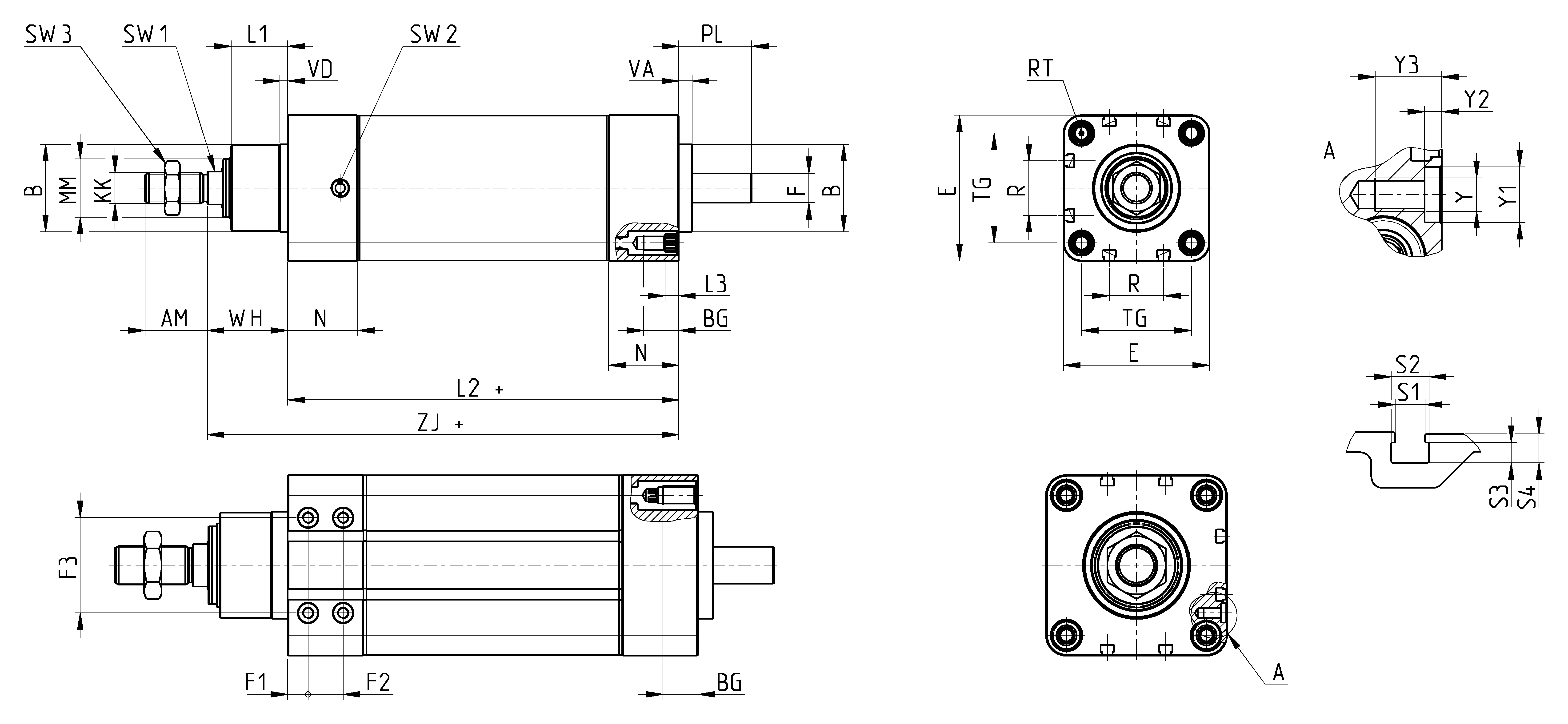
+ = add the stroke
*Dimension not in compliance with ISO 15552 standard
| Size | AM | B | BG | E | F | F1 | F2 | F3 | KK | L1 | L2+ | L3 | MM | N | R | RT | PL | SW1 | SW2 | SW3 | TG | VA | VD | Y | Y1 | Y2 | Y3 | WH | ZJ | S1 | S2 | S3 | S4 | weight stroke 0 [g] | weight stroke [kg/m] |
| 32 | 22 | 30 | 16 | 46,5 | 8 | - | - | - | M10x1,25 | 20 | 125 | 5,5 | 18 | 26 | 13 | M6 | 21 | 10 | G1/8 | 17 | 32,5 | 6 | 4 | - | - | - | - | 30 | 155 | 5,4 | 6,8 | 3,65 | 5 | 1175 | 3,77 |
| 40 | 24 | 35 | 16 | 55,4 | 10 | - | - | - | M12x1,25 | 22 | 142 | 5,5 | 22 | 27 | 13,5 | M6 | 24 | 13 | G1/8 | 19 | 38 | 6 | 4 | - | - | - | - | 33 | 175 | 5,4 | 6,8 | 3,65 | 5 | 1395 | 5,30 |
| 50 | 32 | 40 | 16 | 64,9 | 12 | - | - | - | M16x1,5 | 26 | 173 | 5,5 | 25 | 36 | 16 | M8 | 30 | 17 | G1/8 | 24 | 46,5 | 7 | 4 | - | - | - | - | 38 | 211 | 5,4 | 6,8 | 3,65 | 5 | 2280 | 6,03 |
| 63 | 32 | 45 | 16 | 75 | 15 | - | - | - | M16x1,5 | 29 | 201 | 5,5 | 30 | 36 | 28 | M8 | 38 | 17 | G1/8 | 24 | 56,5 | 7 | 4 | - | - | - | - | 42 | 242,5 | 5,4 | 6,8 | 3,65 | 5 | 3500 | 9,77 |
| 80 | 40 | 55* | 18 | 93 | 19 | 10,5 | 18 | 49 | M20x1,5 | 35 | 211 | - | 40 | 39 | 30 | M10 | 39 | 22 | G1/4 | 30 | 72 | 8 | 8 | M6 | 10 | 3 | 12 | 49 | 260 | 5,4 | 6,8 | 3,65 | 5 | 6440 | 13,70 |
| 100 | 40 | 65* | 18 | 115 | 24 | 13 | 18 | 62 | M20x1,5 | 38 | 232 | - | 50 | 44 | 40 | M10 | 42 | 22 | G1/4 | 30 | 89 | 8 | 8 | M8 | 12 | 3 | 16 | 51 | 283 | 5,4 | 6,8 | 3,65 | 5 | 10725 | 20,50 |

1-16/30 results


.jpg "Mod. D-E")


.jpg "Mod. C")
.jpg "Mod. C-H")


.jpg "Mod. R")


